
Datasheet


Electrical Specifications
Datasheet 27
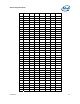
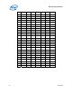
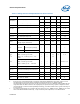
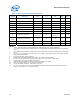
Table 7. Voltage and Current Specifications for the Processors
Symbol Parameter Min Typ Max Unit Notes
13
FSB
Frequency
BCLK Frequency 132.63 133.33 133.37 MHz
V
CC
HFM V
CC
at Highest Frequency Mode (HFM) AVID - 1.10 V 1, 2, 11
V
CC
LFM V
CC
at Lowest Frequency Mode (LFM) 0.75 — AVID V 1, 2
V
CC
,
BOOT
Default V
CC
Voltage for Initial Power
Up
— 1.20 — V 2, 6
V
CCP
AGTL+ Termination Voltage 1.00 1.05 1.10 V
V
CCA
PLL Supply voltage 1.425 1.5 1.575 V
V
CCDPRSLP
V
CC
at Deeper Sleep (C4) 0.75 — 1.0 V 1, 2
V
CCF
Fuse Power Supply 1.00 1.05 1.10 V
I
CCDES
I
CC
for Processors Recommended
Design Target (Estimated)
— — 4.0 A
I
CC
for Processors — — — — —
Processor
Number
Core Frequency/Voltage — — — — —
I
CC
N270 1.6GHz / 1.10V
— — 3 A 3, 4
I
AH,
I
SGNT
I
CC
Auto-Halt & Stop-Grant
HFM: 1.6 GHz @ 1.10 Volts
LFM: 0.8 – 1.2 GHz @ 0.75 – 1.00
Volts
—
—
—
—
2.2
1.5
A 3, 4
I
DSLP
I
CC
Deep Sleep
HFM: 1.6 GHz @ 1.10 Volts
LFM: 0.8 GHz @ 0.75 – 1.00 Volts
—
—
—
—
1.4
0.6
A At 50°C 3, 4
I
DPRSLP
I
CC
Deeper Sleep (C4) — — 0.2 A At 50°C 3, 4
dI
CC
/dt
V
CC
Power Supply Current Slew Rate
at Processor Package Pin (Estimated)
— — 2.5 A/µs 5, 7
I
CCA
I
CC
for V
CCA
Supply — — 130 mA
I
CCP
I
CCP
before V
CC
Stable — — 2.5 A 8
I
CCP
I
CCP
after V
CC
Stable — — 1.5 A 9
NOTES:
1. Each processor is programmed with a maximum valid voltage identification value (VID), which is set at
manufacturing and can not be altered. Individual maximum VID values are calibrated during
manufacturing such that two processors at the same frequency may have different settings within the VID
range. Note that this differs from the VID employed by the processor during a power management event
(Thermal Monitor 2, Enhanced Intel SpeedStep technology, or Enhanced Halt State). Typical AVID range is
0.8 V to 0.85 V.
2. The voltage specifications are assumed to be measured across VCC_SENSE and VSS_SENSE pins at socket
with a 100-MHz bandwidth oscilloscope, 1.5-pF maximum probe capacitance, and 1-MΩ minimum