ATX12V Power Supply Design Guide Version 2.
ATX12V Power Supply Design Guide Version 2.0 IMPORTANT INFORMATION AND DISCLAIMERS INTEL CORPORATION (AND ANY CONTRIBUTOR) IS PROVIDING THIS INFORMATION AS A CONVENIENCE AND ACCORDINGLY MAKES NO WARRANTIES WITH REGARD TO THIS DOCUMENT OR PRODUCTS MADE IN CONFORMANCE WITH THIS DOCUMENT. THIS DOCUMENT IS PROVIDED "AS IS" AND INTEL DISCLAIMS ALL EXPRESS AND IMPLIED WARRANTIES, INCLUDING THE WARRANTY OF MERCHANTABILITY AND FITNESS FOR PARTICULAR PURPOSE.
ATX12V Power Supply Design Guide Version 2.0 Contents 1. Introduction ....................................................................................................... 6 1.1. Scope .....................................................................................................................................6 1.2. Key Changes for ATX12V Version 2.0 as Compared with ATX Power Supply......................6 1.2.1. Increased +12 VDC output capability .................................................
ATX12V Power Supply Design Guide Version 2.0 3.4.3. 3.4.4. 3.4.5. 3.4.6. No-load Operation .....................................................................................................26 Over-current Protection .............................................................................................26 Over-temperature Protection .....................................................................................27 Output Bypass .................................................................
ATX12V Power Supply Design Guide Version 2.0 Figures Figure 1. Cross Loading Graph for 250W Configuration .......................................................................13 Figure 2. Cross Loading Graph for 300W Configuration .......................................................................14 Figure 3. Cross Loading Graph for 350W Configuration .......................................................................15 Figure 4. Cross Loading Graph for 400W Configuration ........................
ATX12V Power Supply Design Guide Version 2.0 1. Introduction 1.1. Scope This document provides design suggestions and reference specifications for a family of power supplies that comply with the ATX Specification, Version 2.03† for motherboards and chassis.
ATX12V Power Supply Design Guide Version 2.0 1.2.3. Main Power Connector: The 2 x 10 main power connector has been replaced by a 2 x 12 connector. This was made to support 75 watt PCI Express*requirements. Pinout assignments are based on the SSI recommendation. With the added 12V, 5V, and 3.3V pins the need for an Aux Power connector is no longer needed and the guidance for this connector has been removed. 1.2.4.
ATX12V Power Supply Design Guide Version 2.0 2. Applicable Documents The following documents support this design guide as additional reference material.
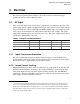
ATX12V Power Supply Design Guide Version 2.0 3. Electrical The electrical requirements that follow are to be met over the environmental ranges specified in Section 5 unless otherwise noted. 3.1. AC Input Table 1 lists AC input voltage and frequency requirements for continuous operation. The power supply shall be capable of supplying full-rated output power over two input voltage ranges rated 100-127 VAC and 200-240 VAC RMS nominal.
ATX12V Power Supply Design Guide Version 2.0 3.1.3. Input Under-voltage The power supply shall contain protection circuitry such that the application of an input voltage below the minimum specified in Section 3.1, Table 1, shall not cause damage to the power supply. 3.1.4. Regulatory The power supply is required to be tested and comply with the most current version of the following regulatory specification requirements and/or standards PRODUCT SAFETY UL* 60950, 3rd Edition –CAN/CSA-C22.
ATX12V Power Supply Design Guide Version 2.0 3.1.5. Catastrophic Failure Protection Should a component failure occur, the power supply should not exhibit any of the following: • Flame • Excessive smoke • Charred PCB • Fused PCB conductor • Startling noise • Emission of molten material 3.2. DC Output 3.2.1.
ATX12V Power Supply Design Guide Version 2.0 3.2.2. Remote Sensing The +3.3 VDC output should have provisions for remote sensing to compensate for excessive cable drops. The default sense should be connected to pin 11 of the main power connector. The power supply should draw no more than 10 mA through the remote sense line to keep DC offset voltages to a minimum. 3.2.3. Typical Power Distribution DC output power requirements and distributions will vary based on specific system options and implementation.
ATX12V Power Supply Design Guide Version 2.0 3.2.3.1. ATX12V Configurations Table 3. Typical Power Distribution for a 250 W ATX12V Configuration Min. Current (amps) Output Max. Current (amps) Peak Current (amps) 10 +12 V1DC 1 8 +12 V2DC 1 14 +5 VDC 0.3 18 +3.3 VDC 0.5 17 -12 VDC 0 0.3 +5 VSB 0 2 2.5 Note: Total combined output of 3.
ATX12V Power Supply Design Guide Version 2.0 Table 4. Typical Power Distribution for a 300 W ATX12V Configuration Min. Current (amps) Max. Current (amps) Peak Current (amps) +12 V1DC 1.0 8.0 10.0 +12 V2DC 1.0 14.0 +5 VDC 0.3 20.0 +3.3 VDC 0.5 20.0 -12 VDC 0.0 0.3 +5 VSB 0.0 2.0 Output 2.5 Note: Total combined output of 3.
ATX12V Power Supply Design Guide Version 2.0 Table 5. Typical Power Distribution for a 350 W ATX12V Configuration Min. Current (amps) Max. Current (amps) Peak Current (amps) +12 V1DC 1 10 12 +12 V2DC 1 15 +5 VDC 0.3 21 +3.3 VDC 0.5 22 -12 VDC 0.0 0.3 Output +5 VSB 0.0 2.0 2.5 Note: Total combined output of 3.
ATX12V Power Supply Design Guide Version 2.0 Table 6. Typical Power Distribution for a 400 W ATX12V Configuration Output Min. Current (amps) Max. Current (amps) +12 V1DC 1 14 +12 V2DC 1 15 +5 VDC 0.3 28 +3.3 VDC 0.5 30 -12 VDC 0 0.3 +5 VSB 0 2 Peak Current (amps) 16 2.5 Note: Total combined output of 3.
ATX12V Power Supply Design Guide Version 2.0 3.2.4. Power Limit / Hazardous Energy Levels Under normal or overload conditions, no output shall continuously provide 240 VA under any conditions of load including output short circuit, per the requirement of UL 1950/CSA 950 / EN 60950/IEC 950. 3.2.5. Efficiency 3.2.5.1. General The power supply required minimum is 70% efficient under “Full” load, 70% under “typical” load, and 60% in a “light” load or idle condition.
ATX12V Power Supply Design Guide Version 2.0 Table 8. Loading Table for Efficiency Measurements 250W (loading shown in Amps) Loading +12V1 +12V2 +5V +3.3V -12V +5Vsb Full 4 11.5 6.8 6.5 0.3 1.0 Typical 3 5 3 4 0.1 1.0 Light 2 2.4 0.3 0.5 0.0 1.0 300W (loading shown in Amps) Loading +12V1 +12V2 +5V +3.3V -12V +5Vsb Full 7 12 8 7.5 0.2 1.0 Typical 4 8 3 4 0.1 1.0 Light 2 2 0.5 1.5 0.0 1.0 350W (loading shown in Amps) Loading +12V1 +12V2 +5V +3.
ATX12V Power Supply Design Guide Version 2.0 3.2.5.2. Energy Star* The “Energy Star” efficiency requirements of the power supply depend on the intended system configuration. In the low-power / sleep state (S1 or S3) the system should consume power in accordance with the values listed inTable 9. Table 9.
ATX12V Power Supply Design Guide Version 2.0 Table 10. DC Output Noise/Ripple Max. Ripple & Noise (mVpp) Output +12 V1DC 120 +12 V2DC 200 +5 VDC 50 +3.3 VDC 50 -12 VDC 120 +5 VSB 50 V out Power Supply AC Hot AC Neutral V return 10uf 0.1uf Load Load must be isolated from the ground of the power supply. AC Ground General Notes: 1. Load the output with its minimum load current. 2. Connect the probes as shown. 3. Repeat the measurement with maximum load on the output.
ATX12V Power Supply Design Guide Version 2.0 3.2.7. Output Transient Response Table 11 summarizes the expected output transient step sizes for each output. The transient load slew rate is = 1.0 A/µs. Table 11. DC Output Transient Step Sizes Max. step size (1) (% of rated output amps per Sec 3.2.3) Output (1) +12 V1DC 40% +12 V2DC 60% +5 VDC 30% +3.3 VDC 30% Max. step size (amps) -12 VDC 0.1 A +5 VSB 0.
ATX12V Power Supply Design Guide Version 2.0 3.2.9. Closed-loop Stability The power supply shall be unconditionally stable under all line/load/transient load conditions including capacitive loads specified in Section 3.2.8. A minimum of 45 degrees phase margin and 10 dB gain margin is recommended at both the maximum and minimum loads. 3.2.10. +5 VDC / +3.3 VDC Power Sequencing The +12 VDC and +5 VDC output levels must be equal to or greater than the +3.
ATX12V Power Supply Design Guide Version 2.0 3.3.1. PWR_OK PWR_OK is a “power good” signal. It should be asserted high by the power supply to indicate that the +12 VDC, +5VDC, and +3.3VDC outputs are above the under-voltage thresholds listed in Section 3.2.1 and that sufficient mains energy is stored by the converter to guarantee continuous power operation within specification for at least the duration specified in Section 3.2.11, “Voltage Hold-up Time.
ATX12V Power Supply Design Guide Version 2.0 Table 14. PS_ON# Signal Characteristics VIL, Input Low Voltage Min. Max. 0.0 V 0.8 V IIL, Input Low Current (Vin = 0.4 V) -1.6 mA VIH, Input High Voltage (Iin = -200 µA) 2.0 V VIH open circuit, Iin = 0 5.25 V Hysteresis ≥ 0.3 V Disable ≥ 2.0 V PS is disabled ≤ 0.8 V PS is enabled Enable 0.8 2.0 5.25 = Maximum OpenCircuit Voltage PS_ON# Voltage Figure 7. PS_ON# Signal Characteristics 3.3.3.
ATX12V Power Supply Design Guide Version 2.0 3.3.4. Power-on Time The power-on time is defined as the time from when PS_ON# is pulled low to when the +12 VDC, +5 VDC, and +3.3 VDC outputs are within the regulation ranges specified in Section 3.2.1. The power-on time shall be less than 500 ms (T1 < 500 ms). +5 VSB shall have a power-on time of two seconds maximum after application of valid AC voltages. 3.3.5.
ATX12V Power Supply Design Guide Version 2.0 3.4. Output Protection 3.4.1. Over-voltage Protection The over-voltage sense circuitry and reference shall reside in packages that are separate and distinct from the regulator control circuitry and reference. No single point fault shall be able to cause a sustained over-voltage condition on any or all outputs. The supply shall provide latch-mode over-voltage protection as defined in Table 15. Table 15. Overvoltage Protection Output Min. Nom. 13.4 15.0 15.
ATX12V Power Supply Design Guide Version 2.0 3.4.5. Over-temperature Protection The power supply may include an over-temperature protection sensor, which can trip and shut down the power supply at a preset temperature point. Such an overheated condition is typically the result of internal current overloading or a cooling fan failure. If the protection circuit is nonlatching, then it should have hysteresis built in to avoid intermittent tripping. 3.4.6.
ATX12V Power Supply Design Guide Version 2.0 4. Mechanical 4.1. Labeling / Marking The following is a non-inclusive list of suggested markings for each power supply unit. Product regulation stipulations for sale into various geographies may impose additional labeling requirements. • Manufacturer information: manufacturer’s name, part number, and lot date code, etc.
ATX12V Power Supply Design Guide Version 2.0 . Air inlet grill, 55% open area. Second optional fan may go in this location WIRE HARNESS 16 REF 150 REF 4.0X6 (2X) Optional air inlet area. 53 REF 20.0 (2X) Optional air inlet area. 146.0 140 REF Preferred locations of manufacturer label No. 6-32 UNC-2B THREADED HOLE (4X) Notes; unless otherwise specified: 1. Dimensions are in mm. 2. Drawing is not to scale. 64.0 3. Tolerances: X +/- 1 X.X +/- 0.5 4.
ATX12V Power Supply Design Guide Version 2.0 . Second optional fan may be located in optional venting area or on topside. Optional Venting Area 53 REF WIRE HARNESS 11.0 x 5.0 cutouts (4X); min 6.0 clearance under cutout from inside top cover. 16 REF 150 REF 4.0X6 20.0 (2X) See Note 5. 94.0 5.0 Preferred location of manufacturer label 146.0 140 REF 5.0 Area on top surface inside dotted lines should have 60% minimum open area for proper venting.
ATX12V Power Supply Design Guide Version 2.0 4.3. Airflow / Fan The ATX Specification allows for numerous (and often confusing) possibilities for power supply fan location, direction, speed, and venting. The designer’s choice of a power supply cooling solution depends in part on the targeted end-use system application(s). At a minimum, the power supply design must ensure its own reliable and safe operation. Fan location/direction.
ATX12V Power Supply Design Guide Version 2.0 The ATX Specification offers two options for venting between the power supply and the system interior: • The venting shown in Figure 8 provides the most effective channeled airflow for the power supply itself, with little regard for directly cooling any system components. This venting method is nearly always used in conjunction with a fan that exhausts out the rear of the power supply.
ATX12V Power Supply Design Guide Version 2.0 1 1 13 1 +3.3V +3.3 +3.3V +3.3 COM CO +5V +5V CO COM +5V +5V COM CO PWR_ON PWR_ +5VSB +5V +12V1 +12V +12V1 +12V +3.3V +3.3V +3.3V +3.3 12V -12V COM CO PS_ON# PS_O CO COM COM CO COM CO NC N +5V +5V +5V +5V +5V +5V COM CO Main Power Connector Figure 10.
ATX12V Power Supply Design Guide Version 2.0 4.5.1. ATX Main Power Connector Connector: MOLEX* housing: 24 Pin Molex Mini-Fit Jr. PN# 39-01-2240 or equivalent (Mating motherboard connector is Molex 44206-0007 or equivalent) 18 AWG is suggested for all wires except for the +3.3 V sense return wire, pin 11 (22 AWG). For 300 W configurations, 16 AWG is recommended for all +12 VDC, +5 VDC, +3.3 VDC, and COM. 34 Pin Signal Color Pin Signal Color 1 +3.3VDC Orange 13 +3.3VDC Orange [13] [+3.
ATX12V Power Supply Design Guide Version 2.0 4.5.2. +12 V Power Connector Connector: MOLEX 39-01-2040 or equivalent (Mating motherboard connector is Molex 39-29-9042 or equivalent) Pin Signal 18 AWG Wire Pin Signal 18 AWG Wire 1 COM Black 3 +12V2DC Yellow /Black Stripe 2 COM Black 4 +12V2DC Yellow/ Black Stripe 4.5.3. Peripheral Connector(s) Connector: AMP 1-480424-0 or MOLEX 8981-04P or equivalent. Contacts: AMP 61314-1 or equivalent.
ATX12V Power Supply Design Guide Version 2.0 4.5.4. Serial ATA Power Connector This is a required connector for systems with Serial ATA devices. The detailed requirements for the Serial ATA Power Connector can be found in the “Serial ATA: High Speed Serialized AT Attachment” specification, Section 6.3 “Cables and connector specification”. http://www.serialata.org/ Wire Signal 18 AWG Wire 5 +3.
ATX12V Power Supply Design Guide Version 2.0 5. Environmental The following subsections define recommended environmental specifications and test parameters, based on the typical conditions to which an ATX12V power supply may be subjected during operation or shipment. 5.1. Temperature Operating ambient +10 °C to +50 °C (At full load, with a maximum temperature rate of change of 5 °C/10 minutes, but no more than 10 °C/hr.
ATX12V Power Supply Design Guide Version 2.0 Final Review Copy 5.5. Mechanical Shock Non-operating 50 g, trapezoidal input; velocity change ≥ 170 in/s Three drops on each of six faces are applied to each sample. 5.6. Random Vibration Non-operating 0.01 g²/Hz at 5 Hz, sloping to 0.02 g²/Hz at 20 Hz, and maintaining 0.02 g²/Hz from 20 Hz to 500 Hz. The area under the PSD curve is 3.13 gRMS. The duration shall be 10 minutes per axis for all three axes on all samples. 5.7.
ATX12V Power Supply Design Guide Version 2.0 Final Review Copy 6. Electromagnetic Compatibility The following subsections outline sample product regulations requirements for a typical power supply. Actual requirements will depend on the design, product end use, target geography, and other variables. Consult your company’s Product Safety and Regulations department for more details. 6.1.
ATX12V Power Supply Design Guide Version 2.0 Final Review Copy 6.3. Input Line Current Harmonic Content and Line Flicker For sales in EU (European Union) or Japan the power supply shall meet the requirements of EN61000-3-2 Class D and the Guidelines for the Suppression of Harmonics in Appliances and General Use Equipment Class D for harmonic line current content at full rated power. See Table 16 for the harmonic limits. Table 16.
ATX12V Power Supply Design Guide Version 2.0 Final Review Copy 7. Reliability 7.1. Component De-rating The de-rating process promotes quality and high reliability. All electronic components should be designed with conservative device de-ratings for use in commercial and industrial environments.
ATX12V Power Supply Design Guide Version 2.0 Final Review Copy 8. Safety The following subsections outline sample product regulations requirements for a typical power supply. Actual requirements will depend on the design, product end use, target geography, and other variables. Consult your company’s Product Safety and Regulations department for more details. 8.1.
ATX12V Power Supply Design Guide Version 2.0 Final Review Copy 8.2. International The vendor must provide a complete CB certificate and test report to IEC 60950: 3rd ed., 1999. The CB report must include ALL CB member country national deviations. CB report must include evaluation to EN 60950: 2000. All evaluations and certifications must be for reinforced insulation between primary and secondary circuits. 8.3. Proscribed Materials Cadmium should not be used in painting or plating.