Intel ATX Power Supply Design Guide Version 0.
Intel ATX Power Supply Design Guide Version 0.9 IMPORTANT INFORMATION AND DISCLAIMERS 1. INTEL CORPORATION (AND ANY CONTRIBUTOR) MAKES NO WARRANTIES WITH REGARD TO THIS DOCUMENT AND IN PARTICULAR DOES NOT WARRANT OR REPRESENT THAT THIS DOCUMENT OR ANY PRODUCTS MADE IN CONFORMANCE WITH IT WILL WORK IN THE INTENDED MANNER.
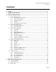
Intel ATX Power Supply Design Guide Version 0.9 Contents 1. Scope .................................................................................................................. 6 2. Applicable Documents ...................................................................................... 7 3. Electrical Specification ..................................................................................... 8 3.1 3.2 3.3 3.4 3.5 AC Input Requirements ....................................................
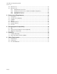
Intel ATX Power Supply Design Guide Version 0.9 4.4 4.5 AC Connector ........................................................................................................................23 DC Connectors ......................................................................................................................23 4.5.1 ATX Main Power Connector .....................................................................................24 4.5.
Intel ATX Power Supply Design Guide Version 0.9 Figures Figure 1: Figure 2: Figure 3: Figure 4: Power Supply Timing .............................................................................................................16 Power Supply Dimensions for Chassis in Which the P/S Does Not Cool Processor ............21 Power Supply Dimensions for Chassis in Which the P/S Cools the Processor.....................22 ATX Power Supply Connectors ..................................................................
Intel ATX Power Supply Design Guide Version 0.9 1. Scope This document outlines a reference ATX power supply that complies with the ATX Specification, Version 2.02 for motherboards and chassis. It is intended to provide additional power supply design information not detailed in the ATX 2.02 specification, including information about the physical form factor of the power supply, cooling requirements, connector configuration, and pertinent electrical and signal timing specifications.
Intel ATX Power Supply Design Guide Version 0.9 2. Applicable Documents The latest revision in effect of the following documents forms a part of this document to the extent specified. AB13-94-146 EACEM European Association of Consumer Electronics Manufacturers. Hazardous Substance List / Certification. ANSI C62.41-1991 IEEE Recommended Practice on Surge Voltages in Low-Voltage AC Circuits. ANSI C62.45-1992 IEEE Guide on Surge Testing for Equipment Connected to Low-Voltage AC Power Circuits.
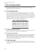
Intel ATX Power Supply Design Guide Version 0.9 3. Electrical Specification The electrical requirements that follow are to be met over the environmental ranges specified in Section 5 unless otherwise noted. 3.1 AC Input Requirements The power supply shall be capable of supplying full rated output power over two input voltage ranges rated 100-127 VAC and 200-240 VAC RMS nominal. The correct input range for use in a given environment may be either switch-selectable or auto-ranging.
Intel ATX Power Supply Design Guide Version 0.9 3.1.4 Immunity 3.1.4.1 Slow Transients The DC output(s) shall not exceed the limits specified in Section 3.2.1 as a result of the input power line noise defined in Table 2 under any load condition per EN 61000-4-11.
Intel ATX Power Supply Design Guide Version 0.9 3.1.4.2.3 Ring Wave, ANSI C62.45-1992 The crest value of the first half peak of the injected oscillatory wave will be 3.0 kV open circuit, with 200 and 500 A short circuit currents for the common and the normal modes of transient surge injection, respectively. No unsafe operation is allowed under any condition. No user-noticeable performance degradation for 1 kV Differential Mode (DM) or 2 kV Common Mode (CM) is allowed.
Intel ATX Power Supply Design Guide Version 0.9 3.1.5 Catastrophic Failure Protection The primary circuit design and the components specified in the same should be such that, should a component failure occur, the power supply should not exhibit any of the following: • Flame • Excessive smoke • Charred PCB • Fused PCB conductor • Startling noise. 3.2 DC Output Requirements 3.2.
Intel ATX Power Supply Design Guide Version 0.9 3.3 Typical Power Distribution Although power requirements and distributions will depend on the specific system options and implementation, this section identifies several potential configurations. For a single processor mini-tower configuration with one ISA slot, three PCI slots, one shared slot, and six peripheral bays, a minimum 160 W sustained (200 W peak) power supply should be sufficient for a typical application.
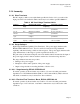
Intel ATX Power Supply Design Guide Version 0.9 Table 6: Typical Power Distribution for a 250 W Configuration Output Min. Current (amps) Max. Current (amps) Peak Current (amps) 12.0 Notes: Requires the 1x6 auxiliary power connector to carry the 3.3 V & 5 V currents to the PCB. +12VDC 0.0 10.0 +5VDC 1.0 25.0 +3.3VDC and +5VDC combined power 145 W Max +3.3VDC 0.3 16.0 Pin 11 default +3.3 V sense required -5VDC 0.0 0.3 -12VDC 0.0 0.8 +5VSB 0.0 0.72 See Section 3.4.3.
Intel ATX Power Supply Design Guide Version 0.9 3.3.3 Output Ripple/Noise The following output ripple/noise requirements should be met throughout the load ranges specified in Section 3.3, and under all input voltage conditions as specified in Section 3.1. Ripple and noise are defined as periodic or random signals over a frequency band of 10 Hz to 20 MHz. Measurements shall be made with an oscilloscope with 20 MHz bandwidth. Outputs should be bypassed at the connector with a 0.
Intel ATX Power Supply Design Guide Version 0.9 3.3.7 +5VDC/+3.3VDC Power Sequencing The +5VDC output level must be equal to or greater than the +3.3VDC output at all times during power-up and normal operation. The time between the +5VDC output reaching its minimum in-regulation level and +3.3VDC reaching its minimum in-regulation level must be less than or equal to 20 ms. 3.3.8 Voltage Hold-up Time The power supply shall maintain output regulation per Section 3.2.
Intel ATX Power Supply Design Guide Version 0.9 3.4 Timing / Housekeeping / Control PS_ON# Off ~ ~ On 95% +5VDC/+3.3VDC O/P 10% T5 ~ PWR_OK T3 T4 T2 PWR_OK Sense Level = 95% of nominal Figure 1: Power Supply Timing Notes: T2 is defined in Section 3.4.5. T3, T4, and T5 are defined in Table 9. 3.4.1 PWR_OK PWR_OK is a “power good” signal. It should be asserted high by the power supply to indicate that the +5VDC and +3.3VDC outputs are above the undervoltage thresholds listed in Section 3.2.
Intel ATX Power Supply Design Guide Version 0.9 3.4.2 PS_ON# PS_ON# is an active-low, TTL-compatible signal that allows a motherboard to remotely control the power supply in conjunction with features such as soft on/off, wake-on-LAN, or wake-on-modem. When PS_ON# is pulled to TTL low, the power supply should turn on the five main DC output rails: +12VDC, +5VDC, +3.3VDC, -5VDC, and -12VDC.
Intel ATX Power Supply Design Guide Version 0.9 3.4.5 Risetime The output voltages shall rise from <10% of nominal to within the regulation ranges specified in Section 3.2.1 within 0.1 ms to 20 ms (0.1 ms ≤ T2 ≤ 20 ms). 3.4.6 Overshoot at Turn-on/Turn-off The output voltage overshoot upon the application or removal of the input voltage, or the assertion/deassertion of PS_ON#, under the conditions specified in Section 3.1, shall be less than 10% above the nominal voltage.
Intel ATX Power Supply Design Guide Version 0.9 3.5 Output Protection 3.5.1 Overvoltage Protection The overvoltage sense circuitry and reference shall reside in packages that are separate and distinct from the regulator control circuitry and reference. No single point fault shall be able to cause a sustained overvoltage condition on any or all outputs. The supply shall provide latch-mode overvoltage protection as defined below. Table 11: Overvoltage Protection Output Min. Nom. +12VDC - - Max. 15.
Intel ATX Power Supply Design Guide Version 0.9 4. Mechanical Requirements 4.1 Labeling / Marking Each supply shall be marked with the following, at minimum: • Access warning text (“Do not remove this cover. Trained service personnel only. No user serviceable components inside.”) in English, German, Spanish, French, Chinese, and Japanese with universal warning markings. • Manufacturer information: manufacturer's name, part number, and lot date code in human-readable text format, etc.
Intel ATX Power Supply Design Guide Version 0.9 Air inlet grill, 55% open area. 53 REF WIRE HARNESS 16 REF 150 REF 4.0X6 (2X) Optional air inlet area. 20.0 (2X) Optional air inlet area. 146.0 140 REF 86 REF 138.0 No. 6-32 UNC-2B THREADED HOLE (4X) Notes; unless otherwise specified: 1. Dimensions are in mm. 2. Drawing is not to scale. 64.0 3. Tolerances: X +/- 1 X.X +/- 0.5 4. If a wire grill is required for acoustics or thermals, the grill and screws must 16.0 be flush mounted. 6.
Intel ATX Power Supply Design Guide Version 0.9 53 REF WIRE HARNESS 11.0 x 5.0 cutouts (4X); min 6.0 clearance under cutout from inside top cover. 16 REF 150 REF 4.0X6 20.0 (2X) See Note 5. 94.0 5.0 146.0 140 REF 5.0 Area on top surface inside dotted lines should have 60% minimum open area for proper venting. Eight rectangular holes are for air duct mounting to direct airflow across processor heatsink. 80.0 45.0 8.0 No. 6-32 UNC-2B THREADED HOLE (4X) Notes; unless otherwise specified: 1.
Intel ATX Power Supply Design Guide Version 0.9 4.3 Airflow / Fan In general, exhausting warm air from the chassis enclosure via a power supply fan at the rear panel is the preferred system-level airflow solution. Other solutions may be implemented, however, and some system/chassis designers may reverse this airflow to meet specific system cooling requirements.
Intel ATX Power Supply Design Guide Version 0.9 +3.3VDC Pin 11 Pin 1 +3.3VDC Pin 1 COM Pin 1 +3.3VDC -12VDC COM COM COM COM +3.3VDC +5VDC PS_ON# +3.
Intel ATX Power Supply Design Guide Version 0.9 4.5.2 Auxiliary Power Connector (for 250 W and 300 W Configurations) Connector: Molex 90331-0010 (keyed pin 6) or equivalent Pin Signal 16 AWG Wire 1 COM Black 2 COM Black 3 COM Black 4 +3.3VDC Orange 5 +3.3VDC Orange 6 +5VDC Red 4.5.3 Peripheral Connector(s) Connector: AMP 1-480424-0 or MOLEX 8981-04P or equivalent. Contacts: AMP 61314-1 or equivalent.
Intel ATX Power Supply Design Guide Version 0.9 5. Environmental Requirements 5.1 Temperature Operating ambient +10 °C min +50 °C max (At full load, with a maximum rate of change of 5 °C/10 minutes, but no more than 10 °C/hr.) Nonoperating ambient -40 °C to +70 °C (Maximum rate of change of 20 °C/hr.) 5.2 Thermal Shock (Shipping) Nonoperating -40 °C to +70 °C; 15 °C/min ≤ dT/dt ≤ 30 °C/min; 50 cycles; Duration of exposure to temperature extremes for each half cycle shall be 30 minutes. 5.
Intel ATX Power Supply Design Guide Version 0.9 5.6 Random Vibration Nonoperating 0.01 g²/Hz at 5 Hz, sloping to 0.02 g²/Hz at 20 Hz, and maintaining 0.02 g²/Hz from 20 Hz to 500 Hz. The area under the PSD curve is 3.13 gRMS. The duration shall be 10 minutes per axis for all three axes on all samples. 5.7 Acoustics Acoustic requirements will be set by the final computer OEM system-level requirements.
Intel ATX Power Supply Design Guide Version 0.9 6. Electromagnetic Compatibility 6.1 EMI The power supply shall comply with CISPR 22, Class B, for both conducted and radiated emissions with a 4 dB margin. Tests shall be conducted using a shielded DC output cable to a shielded load. The load shall be adjusted as follows for three tests: No load on each output; 50% load on each output; and 100% load on each output. Tests will be performed at 100 VAC 50 Hz, 120 VAC 60 Hz, and 220 VAC 50 Hz power. 6.
Intel ATX Power Supply Design Guide Version 0.9 7. Reliability 7.1 Component Derating The following component derating guidelines shall be followed: • Semiconductor junction temperatures shall not exceed 110 °C with an ambient of 50 °C. Any exceptions are subject to final approval. • Inductor case temperature shall not exceed safety agency requirements. • Capacitor case temperature shall not exceed 95% of rated temperature. • Resistor wattage derating shall be > 30%.
Intel ATX Power Supply Design Guide Version 0.9 8. Safety Requirements 8.1 North America The power supply must be certified by UL or CSA for use in the USA and Canada under the following conditions: • The supply must be Recognized for use in Information Technology Equipment including Electrical Business Equipment per UL 1950, 3rd edition, without D3 deviations and CAN/CSA C22.2 no. 950-95.
Intel ATX Power Supply Design Guide Version 0.9 8.2 International The vendor must provide a complete CB certificate and test report to IEC 950, 2nd edition + A1, A2, A3, and A4. The CB report must include ALL CB member country national deviations. CB report must include evaluation to EN60 950, + A1, A2, A3, A4 and EMKO-TSE (74-SEC) 207/94. All evaluations and certifications must be for reinforced insulation between primary and secondary circuits.