How To Use This Manual ATC6430M Mainboard HOW TO USE THIS MANUAL This manual is written in a user-friendly style. It would be advisable for users to read it in an orderly sequence : 1. For Hardware Information: Read COMPONENT LOCATION DIAGRAM, Page A: QUICK JUMPER & CONNECTOR SETTING, Page B: Slot 1 and CPU Installation, Page C: CONNECTORS AND JUMPERS DESCRIPTION and Page D:List of Packaging. 2.
ATC6430M Mainboard Contents CONTENTS QUICK JUMPER & CONNECTOR SETTING..........................A SLOT 1 AND PENTIUM II/III INSTALLATION...................B CONNECTORS AND JUMPERS DESCRIPTION....................C CHECKLIST OF PACKAGING................................................D HOW TO USE THIS MANUAL TABLE OF CONTENTS CHAPTER 1 System Features......................................................1 1-1 Introduction.................................................................... ..........
Contents ATC6430 Mainboard 3-2-5 Power Management Setup......................................................................27 3-2-6 PNP/PCI Configuration..........................................................................31 3-2-7 PC Health Status ...................................................................................33 3-2-8 Frequency / Voltage Control...................................................................34 3-2-9Load Fail-Safe Defaults.......................................
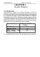
ATC6430M Mainboard Chapter 1 System Features CHAPTER 1 System Features 1-1 Introduction 6430M mainboard is designed to run with Intel 810 chipset to enhance the performance and extraordinary value of the Intel CeleronTM processor-powered PC. On the other hand, it is mounted with both Slot 1 and Socket 370 connector for users to make their CPU choice. It supports 66MHz, 100MHz and 133MHz Host Bus Intel PPGA CeleronTM CPUs.
Chapter 1 System Features ATC 6430M Mainboard 1-2 System Specifications of 6430M Mainboard : CPU Support: u Single CPU, with both Slot 1 and PPGA Socket 370 on board for choice. u Supports CPU Clock 66MHz, 100MHz and 133MHz (133MHz support “Slot 1” socket only). CPU Clock Ratios from 3.0x to 8.0x (step 0.5x). u Supports CPUs : Pentium II 233MHz~450MHz, Celeron 300MHz~500MHz, and Pentium III 450MHz~650MHz. u CPU Core Voltage 1.30V~2.05V (step 0.05V), and 2.1V~3.5V (Step 0.1V); CPU~I/O Voltage 3.3V.
ATC6430M Mainboard Chapter 1 System Features : BIOS Support: u Built-in VGA BIOS in Intel 810; and built-in Keyboard BIOS;. u AWARD BIOS in Intel 810, providing CMOS Setup Utilities: - Standard CMOS Features Setup for Date, Drives and VGA ; - Advanced BIOS Features Setup for CPU Cache, Self Test, Boot Device, Typematic Rate , and Security Options etc.; - Advanced Chipset Features Setup for SDRAM CAS, RAS, System BIOS Cacheable, and Video BIOS Cacheable etc.
Chapter 1 System Features ATC 6430M Mainboard 1-3 Features Highlight 1-3-1 Add-on Features for VGA in Intel 810: : Integrated Graphics Controller u 3D Hyper Pipelined Architecture. u Full 2D H/W Acceleration. u Motion Video Acceleration. : 3D Graphics Visual Enhancements u Flat & Gouraud Shading. u Mip Maps with Bilinear and Anisotropic Filtering. u Fogging Atmospheric Effects. u Z Buffering. u 3D Pipe 2D Clipping. u Backface Culling.
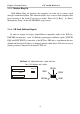
ATC6430M Mainboard 1-3-3 Chapter 1 System Features AMR and AC’97 CODEC Controller AMR slot and AC’97 CODEC are integrated into the Mainboard to enable audio and modem playback. AMR (Audio/Modem Riser) slot is mounted on board to connect riser board with Audio and/or Modem CODEC (AMC/AC/MC Adapters). The AMR specification developed by Intel provides a mechanism for AC’97 codes to be on a riser card. To enable the onboard AC’97 CODEC, set JP9 pin 2-3 closed.
Chapter 1 System Features ATC 6430M Mainboard 1-3-5 Modem Ring On With Modem Ring On function, the computer can wake up by remote signal through a connected modem. This function enables users to access their computer data from anywhere in the world. Users have to enable “Power On by Ring” in “Power Management Setup” of the AWARD BIOS setup screens.
ATC6430M Mainboard Chapter 1 System Features 1-3-7 Ultra DMA 66 Cable (optional) Ultra DMA 66 cable (40-pin connector & 80-line cable) is packaged while utilizing FW82801AA chip which supports both UDMA 33 & UDMA 66 on the mainboard.
Chapter 1 System Features ATC 6430M Mainboard Function” enabled through “ Power Management Setup” from the BIOS setup screen. Caution: For Wake-On-LAN, the +5V standby line for the power supply should be capable of delivering +5V ± 5% at 720mA. Failure to provide adequate standby current when implementing Wake-On-LAN will damage the power supply.
6430M Mainboard Chapter 2 Installation CHAPTER 2 INSTALLATION 2-1 INSTALLATION PROCEDURE Before installing the computer, please prepare all components such as CPU, DRAM; peripherals such as hard drive, keyboard, CD-ROM and accessories such as cables. Then, install the system as following: - Put CPU / heat sink (refer to CeleronTM CPU installation guide or see the following setup chapter), and DRAM modules on the mainboard. Plug add-on cards into PCI slots, if needed.
Chapter 2 Installation 6430M Mainboard 2-2 CPU INSTALLATION This mainboard supports PPGA Socket 370 and Slot 1 processors. The 6430M mainboard has built-in Switching Voltage Regulator to support CPU Vcore autodetection. That is, It is smart enough to detect and recognize the CPU voltage, clock, ratio and enables users to set up the CPU frequency from the BIOS Setup Screen. Users can adjust the frequency through “Frequency / Voltage Control” of the BIOS Setup Screen. A.
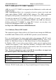
6430M Mainboard Chapter 2 Installation 2-3 SYSTEM MEMORY INSTALLATION 6430M mainboard provides two 3.3V 168-pin DIMM sockets for system memory expansion from 8MB to 512MB SDRAM. These two DIMMs are arranged to two banks, please refer to page A. Bank/DIMM PC-100 Memory Module Bank0/DIMM1 8/16/32/64/128/256MB Bank1/DIMM2 8/16/32/64/128/256MB Total System Memory Total Memory 8MB~256MB 8MB~256MB 8MB~512MB DIMM type, Size, parity supported: 6 6 6 6 PC-66/100 or higher performance memory module.
Chapter 2 Installation 6430M Mainboard 2-4 INTEL 810 DRIVER INSTALLATION Ø INF Files for Windows 95/98 : 1. Start Windows 95/98. 2. Put the All-In-One CD into your CD-ROM drive. 3. Choose Intel 810/820 Inf Files on the Autorun main menu. 4. Then follow the instruction on the screen. (INF Files that enable the Intel 810/820 Chipsets to be recognized by listed operating systems.) 2-5 VGA DRIVER INSTALLATION Install Intel 810 AGP Driver For Win95/98/NT 1. Start Windows 95/98/NT. 2.
ATC6430M Mainboard Chapter 3 Award BIOS Setup CHAPTER 3 AWARD BIOS SETUP Award BIOS manufacturer provides access to the system BIOS through the hardware and software on mainboard. The hardware consists of a Flash ROM (4MB in 6430M mainboard) and the software is a group of programs that are installed in the ROMBIOS along with all the other data that should be included into the BIOS. After the BIOS is updated, if you want to clear the old setup data stored in the CMOS, then you can reset CMOS as follow.
Chapter 3 Award BIOS Setup ATC6430M Mainboard 3-1 UPDATE BIOS PROCEDURE 3-1-1 BIOS Update: If the BIOS needs to be updated, you can get a CD with the updated BIOS utility in the package. The CD includes : “awdflash.exe” -- BIOS update utility program “awdflash.doc” The update procedure is as following: 1. Boot the system to DOS mode in a normal manner. 2. Insert the updated CD to drive D (or E). 3. Change working directory to CD-ROM drive, D or E, which contains the update BIOS CD.
ATC6430M Mainboard Chapter 3 Award BIOS Setup 3-1-2 UPDATE MICROCODE API Intel also provides MICROCODE API (Applications Programming Interface) for mainboard user to update data block in BIOS quickly and easily. (You can find this utility in the All-In-One CD in the mainboard package). The BIOS code on the mainboards contains data that is specific to each silicon stepping of the processor. Integrators must ensure that this BIOS stepping data matches the used processor stepping.
Chapter 3 Award BIOS Setup ATC6430M Mainboard 3-2 SYSTEM BIOS CONFIGURATION SETUP The following pages explain how to set up the BIOS configuration under the Award BIOS. The SETUP program is stored in the Read-Only-Memory (ROM) on the mainboard. To do the SETUP procedure, press the key when the system is booting up. The following main menu will appear. Please select " STANDARD CMOS FEATURE" to enter the next screen.
ATC6430M Mainboard Chapter 3 Award BIOS Setup Control Key Description UP ARROW DOWN ARROW LEFT ARROW RIGHT ARROW Esc KEY Esc PgUp KEY PgDn KEY F1 KEY F5 KEY F6 KEY F7 KEY F10 KEY Help Old Value Load Fail-Safe Defaults Load Optimized Defaults Save & Exit Setup Move to the previous item Move to the next item Move to the item on the left Move to the item on the right Main Menu : Quit without saving changes Setup menu : Exit current page and return to main menu Increase the numeric value or make changes De
Chapter 3 Award BIOS Setup ATC6430M Mainboard 3-2-1 STANDARD CMOS FEATURES This screen records some basic hardware information, and sets the system clock and error handling. These records can be lost or corrupted if the on-board battery has failed or is weak.
ATC6430M Mainboard Chapter 3 Award BIOS Setup IDE Primary Master; Primary Slave Secondary Master; Secondary Slave Press Enter to enter next page for detailed hard drive settings: CMOS Setup Utility – Copyright © 1984-1998 Award Software IDE Primary Master IDE HDD Auto-Detection Press Enter Item Help Menu Level IDE Primary Master Capacity Access Mode Cylinder Head Precomp Landing Zone Sector Auto 2557 MB Auto 4956 16 0 4955 63 ØØ To auto-detect the HDD size, head..
Chapter 3 Award BIOS Setup ATC6430M Mainboard Drive A, Drive B This category identifies the types of floppy disk drive A or drive B that have been installed in the computer. None No floppy drive installed 360K, 5.25 in 5.25“ PC-type 360KB capacity 1.2M, 5.25 in 5.25“ AT-type 1.2MB capacity 720K, 3.5 in 3.5“ double-side 720KB capacity 1.44M, 3.5 in 3.5“ double-side 1.44MB capacity 2.88M, 3.5 in 3.5“ double-side 2.88MB capacity Floppy 3 Mode Support This is the Japanese standard floppy drive.
ATC6430M Mainboard Chapter 3 Award BIOS Setup 3-2-2 ADVANCED BIOS FEATURES This screen is a list of system configuration options. Some of them are defaults required by the mainboard’s design, others depend on the features of your system.
Chapter 3 Award BIOS Setup ATC6430M Mainboard CPU L2 Cache ECC Checking If Enabled, this function will do ECC check to CPU L2 Cache automatically. Quick Power On Self Test This category speeds up Power On Self Test while booting. If “Enabled”, BIOS will skip some items under check by POST. First Boot Device, Second Boot Device, Third Boot Device, Boot Other Device Allows user to select the Boot Device Priority. The choices: Floppy, LS/ZIP/, HDD, SCSI, CDROM, Disabled.
ATC6430M Mainboard Chapter 3 Award BIOS Setup OS Select for DRAM > 64MB This item allows you to access the memory that is over 64MB in OS/2. The choice : Non-OS2, OS2 HDD S.M.A.R.T. Capability Select Enabled if your Hard disk supports S.M.A.R.T.(Safe-Monitoring Analysis and Reporting Technology) function. Report No FDD For WIN 95 Set this item to Yes, BIOS will report FDD to Win95.
Chapter 3 Award BIOS Setup ATC6430M Mainboard 3-2-3 ADVANCED CHIPSET FEATURES This screen controls the setting for the chipset on the mainboard. This chipset manages bus speeds and access to system memory resources.
ATC6430M Mainboard Chapter 3 Award BIOS Setup SDRAM CAS Latency Time When synchronous DRAM is installed, the number of clock cycles of CAS latency depends on the DRAM timing. The choices: 2,3. “2” gives faster performance and “3” gives more stable performance. SDRAM Cycle Time Tras/Trc Select the number of SCLKs for an access cycle. “5/7” gives faster performance and “6/8” gives more stable performance.
Chapter 3 Award BIOS Setup ATC6430M Mainboard page miss. Open: it will precharge bank during the service of a page miss. RAS-to-CAS Override By CAS# LT: the RAS-to-CAS delay timing will be the same as item of CAS# Latency. Override: the value will be fixed in 2. RAS# Timing This item controls the active time of RAS# and bank cycle time. “Fast” gives faster performance and “Slow” gives more stable performance.
ATC6430M Mainboard Chapter 3 Award BIOS Setup 3-2-4 INTEGRATED PERIPHERALS This section page includes all the items of IDE hard drive and Programmed Input/Output features. See also Section “Chipset Features Setup”.
Chapter 3 Award BIOS Setup ATC6430M Mainboard simpler and faster. Your system supports five modes, 0 - 4, which primarily differ in timing. When Auto is selected, the BIOS will select the best available mode. IDE Primary Master/Slave UDMA; IDE Secondary Master/Slave UDMA Auto, will support the Ultra DMA function. Disabled, will not support the Ultra DMA function. USB Controller This item allows you to decide to enable/disable the USB controller.
ATC6430M Mainboard Chapter 3 Award BIOS Setup UART Mode Select This lets you select the Infrared mode. Choices are IrDA, ASKIR, Normal, and SCR. Only when you choose IrDA or ASKIR , the screen will then show “UART2 Duplex Mode’ for you to choose “Full” or “Half”.. On Board Parallel Port Let user select IRQ for parallel port When Disabled, the parallel port will be disabled. Parallel Port Mode Let user select Parallel Port : SPP, EPP, ECP, ECP+EPP ECP Mode Use DMA Select a DMA channel for the port.
Chapter 3 Award BIOS Setup ATC6430M Mainboard 3-2-5 POWER MANAGEMENT SETUP This screen controls the 'green' features of this mainboard.
ATC6430M Mainboard Video Off Method V/H SYNC + Blank Blank Screen DPMS Chapter 3 Award BIOS Setup This determines the manner in which the monitor is blanked. This selection will cause the system to turn off the vertical and horizontal sync. ports and write blanks to the video buffer. This option only writes blanks to the video buffer. Initial of “Display Power Management Signaling”. Video off In Suspend This determines the manner in which the monitor is blanked. Suspend Type Select the suspend type.
Chapter 3 Award BIOS Setup ATC6430M Mainboard 3-2-6 PNP/PCI CONFIGURATION This screen configures the PCI Bus slots. CMOS Setup Utility – Copyright © 1984-1998 Award Software PnP/PCI Configurations PNP OS Installed Reset Configuration Data No Item Help -------------------Disabled Menu Level Ø Resources Controlled By Auto Select “Yes” if you are Ø IRQ Resources Press Enter using a Plug and Play OS.
ATC6430M Mainboard Memory Resources Chapter 3 Award BIOS Setup Length 8K 33
Chapter 3 Award BIOS Setup ATC6430M Mainboard PCI/VGA Snoop It determines whether the MPEG ISA/VGA cards can work with PCI/VGA or not.
ATC6430M Mainboard Chapter 3 Award BIOS Setup 3-2-7 PC Health Status This screen shows your in-use PC Health Condition: CMOS Setup Utility – Copyright © 1984-1998 Award Software PC Health Status Vcore +2.5V +3.3V +5V +12V -12V +1.
Chapter 3 Award BIOS Setup ATC6430M Mainboard 3-2-8 FREQUENCY / VOLTAGE CONTROL This screen controls the 'green' features of this mainboard.
ATC6430M Mainboard Chapter 3 Award BIOS Setup 3-2-9 LOAD FAIL-SAFE DEFAULTS When your mainboard has problems and needs to trouble shoot the system, you can use this function. The default values loaded only affect the BIOS Features Setup, Chipset Features Setup, Power Management Setup and PNP/PCI Configuration Setup. There is no effect on the Standard CMOS Setup. To use this function, select it from main menu and press .