
Desktop 4th Generation Specification Sheet
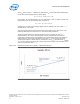
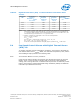


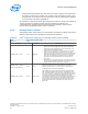
Table Of Contents
- Contents
- Revision History
- 1.0 Introduction
- 2.0 Interfaces
- 3.0 Technologies
- 3.1 Intel® Virtualization Technology (Intel® VT)
- 3.2 Intel® Trusted Execution Technology (Intel® TXT)
- 3.3 Intel® Hyper-Threading Technology (Intel® HT Technology)
- 3.4 Intel® Turbo Boost Technology 2.0
- 3.5 Intel® Advanced Vector Extensions 2.0 (Intel® AVX2)
- 3.6 Intel® Advanced Encryption Standard New Instructions (Intel® AES-NI)
- 3.7 Intel® Transactional Synchronization Extensions - New Instructions (Intel® TSX-NI)
- 3.8 Intel® 64 Architecture x2APIC
- 3.9 Power Aware Interrupt Routing (PAIR)
- 3.10 Execute Disable Bit
- 3.11 Supervisor Mode Execution Protection (SMEP)
- 4.0 Power Management
- 4.1 Advanced Configuration and Power Interface (ACPI) States Supported
- 4.2 Processor Core Power Management
- 4.3 Integrated Memory Controller (IMC) Power Management
- 4.4 PCI Express* Power Management
- 4.5 Direct Media Interface (DMI) Power Management
- 4.6 Graphics Power Management
- 5.0 Thermal Management
- 5.1 Desktop Processor Thermal Profiles
- 5.2 Thermal Metrology
- 5.3 Fan Speed Control Scheme with Digital Thermal Sensor (DTS) 1.1
- 5.4 Fan Speed Control Scheme with Digital Thermal Sensor (DTS) 2.0
- 5.5 Processor Temperature
- 5.6 Adaptive Thermal Monitor
- 5.7 THERMTRIP# Signal
- 5.8 Digital Thermal Sensor
- 5.9 Intel® Turbo Boost Technology Thermal Considerations
- 6.0 Signal Description
- 6.1 System Memory Interface Signals
- 6.2 Memory Reference and Compensation Signals
- 6.3 Reset and Miscellaneous Signals
- 6.4 PCI Express*-Based Interface Signals
- 6.5 Display Interface Signals
- 6.6 Direct Media Interface (DMI)
- 6.7 Phase Locked Loop (PLL) Signals
- 6.8 Testability Signals
- 6.9 Error and Thermal Protection Signals
- 6.10 Power Sequencing Signals
- 6.11 Processor Power Signals
- 6.12 Sense Signals
- 6.13 Ground and Non-Critical to Function (NCTF) Signals
- 6.14 Processor Internal Pull-Up / Pull-Down Terminations
- 7.0 Electrical Specifications
- 8.0 Package Mechanical Specifications
- 9.0 Processor Ball and Signal Information

Figure 21. Digital Thermal Sensor (DTS) Thermal Profile Definition
Table 27. Thermal Margin Slope
PCG Die
Configuration
(Native)
Core + GT
TDP (W) TCC Activation
Temperature (°C)
MSR 1A2h 23:16
Temperature
Control Offset
MSR 1A2h 15:8
Thermal
Margin
Slope
(°C / W)
2013D
4+2 (4+2) 84 100 20 0.654
4+0 (4+2) 82 100 20 0.671
2013C
4+2 (4+2) 65 92 6 0.722
2+2 (2+2) 54 100 20 1.031
2+1 (2+2) 53 100 20 1.051
2013B 4+2 (4+2) 45 85 6 0.806
2013A
4+2 (4+2) 35 75 6 0.806
2+2 (4+2) 35 85 6 1.016
2+2 (2+2) 35 85 6 1.021
2+1 (2+2) 35 90 6 1.141
Processor Temperature
A software readable field in the TEMPERATURE_TARGET register that contains the
minimum temperature at which the TCC will be activated and PROCHOT# will be
asserted. The TCC activation temperature is calibrated on a part-by-part basis and
normal factory variation may result in the actual TCC activation temperature being
higher than the value listed in the register. TCC activation temperatures may change
based on processor stepping, frequency or manufacturing efficiencies.
5.5
Processor—Thermal Management
Desktop 4th Generation Intel
®
Core
™
Processor Family, Desktop Intel
®
Pentium
®
Processor Family, and Desktop Intel
®
Celeron
®
Processor Family
Datasheet – Volume 1 of 2 December 2013
74 Order No.: 328897-004