
Desktop 4th Generation Specification Sheet
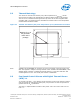
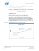


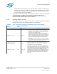
Table Of Contents
- Contents
- Revision History
- 1.0 Introduction
- 2.0 Interfaces
- 3.0 Technologies
- 3.1 Intel® Virtualization Technology (Intel® VT)
- 3.2 Intel® Trusted Execution Technology (Intel® TXT)
- 3.3 Intel® Hyper-Threading Technology (Intel® HT Technology)
- 3.4 Intel® Turbo Boost Technology 2.0
- 3.5 Intel® Advanced Vector Extensions 2.0 (Intel® AVX2)
- 3.6 Intel® Advanced Encryption Standard New Instructions (Intel® AES-NI)
- 3.7 Intel® Transactional Synchronization Extensions - New Instructions (Intel® TSX-NI)
- 3.8 Intel® 64 Architecture x2APIC
- 3.9 Power Aware Interrupt Routing (PAIR)
- 3.10 Execute Disable Bit
- 3.11 Supervisor Mode Execution Protection (SMEP)
- 4.0 Power Management
- 4.1 Advanced Configuration and Power Interface (ACPI) States Supported
- 4.2 Processor Core Power Management
- 4.3 Integrated Memory Controller (IMC) Power Management
- 4.4 PCI Express* Power Management
- 4.5 Direct Media Interface (DMI) Power Management
- 4.6 Graphics Power Management
- 5.0 Thermal Management
- 5.1 Desktop Processor Thermal Profiles
- 5.2 Thermal Metrology
- 5.3 Fan Speed Control Scheme with Digital Thermal Sensor (DTS) 1.1
- 5.4 Fan Speed Control Scheme with Digital Thermal Sensor (DTS) 2.0
- 5.5 Processor Temperature
- 5.6 Adaptive Thermal Monitor
- 5.7 THERMTRIP# Signal
- 5.8 Digital Thermal Sensor
- 5.9 Intel® Turbo Boost Technology Thermal Considerations
- 6.0 Signal Description
- 6.1 System Memory Interface Signals
- 6.2 Memory Reference and Compensation Signals
- 6.3 Reset and Miscellaneous Signals
- 6.4 PCI Express*-Based Interface Signals
- 6.5 Display Interface Signals
- 6.6 Direct Media Interface (DMI)
- 6.7 Phase Locked Loop (PLL) Signals
- 6.8 Testability Signals
- 6.9 Error and Thermal Protection Signals
- 6.10 Power Sequencing Signals
- 6.11 Processor Power Signals
- 6.12 Sense Signals
- 6.13 Ground and Non-Critical to Function (NCTF) Signals
- 6.14 Processor Internal Pull-Up / Pull-Down Terminations
- 7.0 Electrical Specifications
- 8.0 Package Mechanical Specifications
- 9.0 Processor Ball and Signal Information
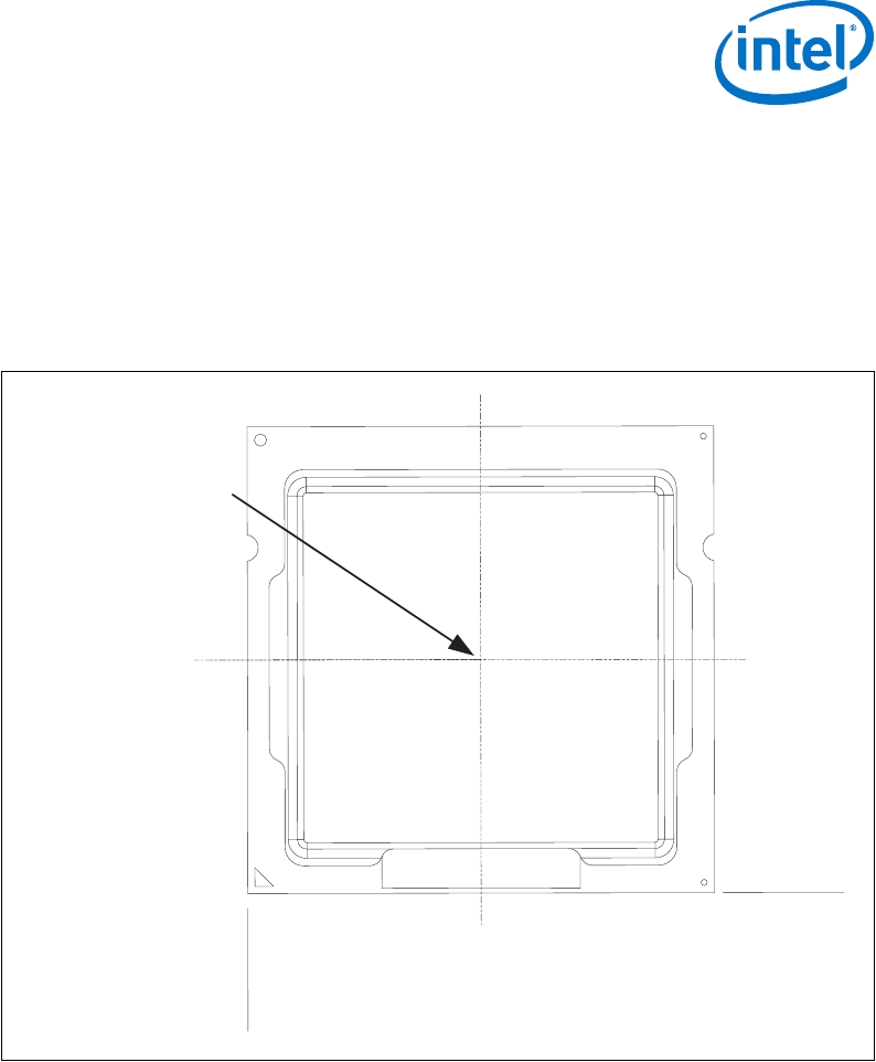
Thermal Metrology
The maximum Thermal Test Vehicle (TTV) case temperatures (T
CASE-MAX
) can be
derived from the data in the appropriate TTV thermal profile earlier in this chapter.
The TTV T
CASE
is measured at the geometric top center of the TTV integrated heat
spreader (IHS). The following figure illustrates the location where T
CASE
temperature
measurements should be made.
Figure 19. Thermal Test Vehicle (TTV) Case Temperature (T
CASE
) Measurement Location
37.5
37.5
Measure T
CASE
at
the geometric
center of the
package
Note: THERM-X OF CALIFORNIA can machine the groove and attach a thermocouple to the
IHS. The supplier is subject to change without notice. THERM-X OF CALIFORNIA, 1837
Whipple Road, Hayward, Ca 94544. Ernesto B Valencia +1-510-441-7566 Ext. 242
ernestov@therm-x.com. The vendor part number is XTMS1565.
Fan Speed Control Scheme with Digital Thermal Sensor
(DTS) 1.1
To correctly use DTS 1.1, the designer must first select a worst case scenario T
AMBIENT
,
and ensure that the Fan Speed Control (FSC) can provide a Ψ
CA
that is equivalent or
greater than the Ψ
CA
specification.
The DTS 1.1 implementation consists of two points: a Ψ
CA
at T
CONTROL
and a Ψ
CA
at
DTS = -1.
5.2
5.3
Thermal Management—Processor
Desktop 4th Generation Intel
®
Core
™
Processor Family, Desktop Intel
®
Pentium
®
Processor Family, and Desktop Intel
®
Celeron
®
Processor Family
December 2013 Datasheet – Volume 1 of 2
Order No.: 328897-004 71