
Desktop 4th Generation Specification Sheet


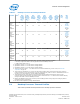
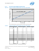
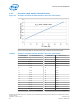
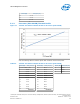
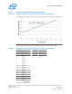
Table Of Contents
- Contents
- Revision History
- 1.0 Introduction
- 2.0 Interfaces
- 3.0 Technologies
- 3.1 Intel® Virtualization Technology (Intel® VT)
- 3.2 Intel® Trusted Execution Technology (Intel® TXT)
- 3.3 Intel® Hyper-Threading Technology (Intel® HT Technology)
- 3.4 Intel® Turbo Boost Technology 2.0
- 3.5 Intel® Advanced Vector Extensions 2.0 (Intel® AVX2)
- 3.6 Intel® Advanced Encryption Standard New Instructions (Intel® AES-NI)
- 3.7 Intel® Transactional Synchronization Extensions - New Instructions (Intel® TSX-NI)
- 3.8 Intel® 64 Architecture x2APIC
- 3.9 Power Aware Interrupt Routing (PAIR)
- 3.10 Execute Disable Bit
- 3.11 Supervisor Mode Execution Protection (SMEP)
- 4.0 Power Management
- 4.1 Advanced Configuration and Power Interface (ACPI) States Supported
- 4.2 Processor Core Power Management
- 4.3 Integrated Memory Controller (IMC) Power Management
- 4.4 PCI Express* Power Management
- 4.5 Direct Media Interface (DMI) Power Management
- 4.6 Graphics Power Management
- 5.0 Thermal Management
- 5.1 Desktop Processor Thermal Profiles
- 5.2 Thermal Metrology
- 5.3 Fan Speed Control Scheme with Digital Thermal Sensor (DTS) 1.1
- 5.4 Fan Speed Control Scheme with Digital Thermal Sensor (DTS) 2.0
- 5.5 Processor Temperature
- 5.6 Adaptive Thermal Monitor
- 5.7 THERMTRIP# Signal
- 5.8 Digital Thermal Sensor
- 5.9 Intel® Turbo Boost Technology Thermal Considerations
- 6.0 Signal Description
- 6.1 System Memory Interface Signals
- 6.2 Memory Reference and Compensation Signals
- 6.3 Reset and Miscellaneous Signals
- 6.4 PCI Express*-Based Interface Signals
- 6.5 Display Interface Signals
- 6.6 Direct Media Interface (DMI)
- 6.7 Phase Locked Loop (PLL) Signals
- 6.8 Testability Signals
- 6.9 Error and Thermal Protection Signals
- 6.10 Power Sequencing Signals
- 6.11 Processor Power Signals
- 6.12 Sense Signals
- 6.13 Ground and Non-Critical to Function (NCTF) Signals
- 6.14 Processor Internal Pull-Up / Pull-Down Terminations
- 7.0 Electrical Specifications
- 8.0 Package Mechanical Specifications
- 9.0 Processor Ball and Signal Information

Table 21. Desktop Processor Thermal Specifications
Product PCG
8
Max
Power
Packag
e C1E
(W)
1, 2,
5, 9
Max
Power
Packag
e C3
(W)
1, 3,
5, 9
Min
Power
Package
C3 (W)
9
Max
Power
Packag
e C6
(W)
1, 4,
5, 9
Max
Power
Package
C7 (W)
1,
4, 5, 9
Min
Power
Package
C6/C7
(W)
9
TTV
Thermal
Design
Power
(W)
6, 7,
10
Min
T
CASE
(°C)
Max
TTV
T
CASE
(°C)
Quad
Core
Processor
with
Graphics
2013D 26 20 1.0 3.5 3.4 0 84 5
Processo
r (PCG
2013D)
Thermal
Profile
on page
67
Quad
Core
Processor
with
Graphics
2013C 23 17 1.0 3.5 3.4 0 65 5
Processo
r (PCG
2013C)
Thermal
Profile
on page
68
Quad
Core
Processor
with
Graphics
2013B 18 11 1.0 3.5 3.4 0 45 5
Processo
r (PCG
2013B)
Thermal
Profile
on page
69
Quad
Core
Processor
with
Graphics
2013A
16 16 1.0 3.5 3.4 0 35 5
Processo
r (PCG
2013A)
Thermal
Profile
on page
70
Dual Core
Processor
with
Graphics
16 16 1.0 3.5 3.4 0 35 5
Notes: 1. The package C-state power is the worst case power in the system configured as follows:
a. Memory configured for DDR3 1333 and populated with two DIMMs per channel.
b. DMI and PCIe links are at L1.
2. Specification at DTS = 50 °C and minimum voltage loadline.
3. Specification at DTS = 50 °C and minimum voltage loadline.
4. Specification at DTS = 35 °C and minimum voltage loadline.
5. These DTS values in Notes 2 – 4 are based on the TCC Activation MSR having a value of 100, see Processor
Temperature on page 74.
6. These values are specified at V
CC_MAX
and V
NOM
for all other voltage rails for all processor frequencies. Systems
must be designed to ensure the processor is not to be subjected to any static V
CC
and I
CC
combination wherein V
CCP
exceeds V
CCP_MAX
at specified I
CCP
. See the loadline specifications.
7. Thermal Design Power (TDP) should be used for processor thermal solution design targets. TDP is not the
maximum power that the processor can dissipate. TDP is measured at DTS = -1. TDP is achieved with the Memory
configured for DDR3 1333 and 2 DIMMs per channel.
8. Platform Compatibility Guide (PCG) (previously known as FMB) provides a design target for meeting all planned
processor frequency requirements.
9. Not 100% tested. Specified by design characterization.
Desktop Processor Thermal Profiles
This section provides thermal profiles for the Desktop processor families.
5.1
Processor—Thermal Management
Desktop 4th Generation Intel
®
Core
™
Processor Family, Desktop Intel
®
Pentium
®
Processor Family, and Desktop Intel
®
Celeron
®
Processor Family
Datasheet – Volume 1 of 2 December 2013
66 Order No.: 328897-004