
Desktop 4th Generation Specification Sheet

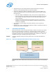
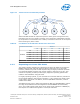

Table Of Contents
- Contents
- Revision History
- 1.0 Introduction
- 2.0 Interfaces
- 3.0 Technologies
- 3.1 Intel® Virtualization Technology (Intel® VT)
- 3.2 Intel® Trusted Execution Technology (Intel® TXT)
- 3.3 Intel® Hyper-Threading Technology (Intel® HT Technology)
- 3.4 Intel® Turbo Boost Technology 2.0
- 3.5 Intel® Advanced Vector Extensions 2.0 (Intel® AVX2)
- 3.6 Intel® Advanced Encryption Standard New Instructions (Intel® AES-NI)
- 3.7 Intel® Transactional Synchronization Extensions - New Instructions (Intel® TSX-NI)
- 3.8 Intel® 64 Architecture x2APIC
- 3.9 Power Aware Interrupt Routing (PAIR)
- 3.10 Execute Disable Bit
- 3.11 Supervisor Mode Execution Protection (SMEP)
- 4.0 Power Management
- 4.1 Advanced Configuration and Power Interface (ACPI) States Supported
- 4.2 Processor Core Power Management
- 4.3 Integrated Memory Controller (IMC) Power Management
- 4.4 PCI Express* Power Management
- 4.5 Direct Media Interface (DMI) Power Management
- 4.6 Graphics Power Management
- 5.0 Thermal Management
- 5.1 Desktop Processor Thermal Profiles
- 5.2 Thermal Metrology
- 5.3 Fan Speed Control Scheme with Digital Thermal Sensor (DTS) 1.1
- 5.4 Fan Speed Control Scheme with Digital Thermal Sensor (DTS) 2.0
- 5.5 Processor Temperature
- 5.6 Adaptive Thermal Monitor
- 5.7 THERMTRIP# Signal
- 5.8 Digital Thermal Sensor
- 5.9 Intel® Turbo Boost Technology Thermal Considerations
- 6.0 Signal Description
- 6.1 System Memory Interface Signals
- 6.2 Memory Reference and Compensation Signals
- 6.3 Reset and Miscellaneous Signals
- 6.4 PCI Express*-Based Interface Signals
- 6.5 Display Interface Signals
- 6.6 Direct Media Interface (DMI)
- 6.7 Phase Locked Loop (PLL) Signals
- 6.8 Testability Signals
- 6.9 Error and Thermal Protection Signals
- 6.10 Power Sequencing Signals
- 6.11 Processor Power Signals
- 6.12 Sense Signals
- 6.13 Ground and Non-Critical to Function (NCTF) Signals
- 6.14 Processor Internal Pull-Up / Pull-Down Terminations
- 7.0 Electrical Specifications
- 8.0 Package Mechanical Specifications
- 9.0 Processor Ball and Signal Information

Note: When P_LVLx I/O instructions are used, MWAIT sub-states cannot be defined. The
MWAIT sub-state is always zero if I/O MWAIT redirection is used. By default, P_LVLx
I/O redirections enable the MWAIT 'break on EFLAGS.IF’ feature that triggers a
wakeup on an interrupt, even if interrupts are masked by EFLAGS.IF.
Core C-State Rules
The following are general rules for all core C-states, unless specified otherwise:
• A core C-state is determined by the lowest numerical thread state (such as Thread
0 requests C1E state while Thread 1 requests C3 state, resulting in a core C1E
state). See the G, S, and C Interface State Combinations table.
• A core transitions to C0 state when:
— An interrupt occurs
— There is an access to the monitored address if the state was entered using an
MWAIT/Timed MWAIT instruction
— The deadline corresponding to the Timed MWAIT instruction expires
• An interrupt directed toward a single thread wakes only that thread.
• If any thread in a core is in active (in C0 state), the core's C-state will resolve to
C0 state.
• Any interrupt coming into the processor package may wake any core.
• A system reset re-initializes all processor cores.
Core C0 State
The normal operating state of a core where code is being executed.
Core C1/C1E State
C1/C1E is a low power state entered when all threads within a core execute a HLT or
MWAIT(C1/C1E) instruction.
A System Management Interrupt (SMI) handler returns execution to either Normal
state or the C1/C1E state. See the Intel
®
64 and IA-32 Architectures Software
Developer’s Manual for more information.
While a core is in C1/C1E state, it processes bus snoops and snoops from other
threads. For more information on C1E state, see Package C-States on page 55.
Core C3 State
Individual threads of a core can enter the C3 state by initiating a P_LVL2 I/O read to
the P_BLK or an MWAIT(C3) instruction. A core in C3 state flushes the contents of its
L1 instruction cache, L1 data cache, and L2 cache to the shared L3 cache, while
maintaining its architectural state. All core clocks are stopped at this point. Because
the core’s caches are flushed, the processor does not wake any core that is in the C3
state when either a snoop is detected or when another core accesses cacheable
memory.
4.2.4
Processor—Power Management
Desktop 4th Generation Intel
®
Core
™
Processor Family, Desktop Intel
®
Pentium
®
Processor Family, and Desktop Intel
®
Celeron
®
Processor Family
Datasheet – Volume 1 of 2 December 2013
54 Order No.: 328897-004