
Desktop 4th Generation Specification Sheet
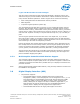


Table Of Contents
- Contents
- Revision History
- 1.0 Introduction
- 2.0 Interfaces
- 3.0 Technologies
- 3.1 Intel® Virtualization Technology (Intel® VT)
- 3.2 Intel® Trusted Execution Technology (Intel® TXT)
- 3.3 Intel® Hyper-Threading Technology (Intel® HT Technology)
- 3.4 Intel® Turbo Boost Technology 2.0
- 3.5 Intel® Advanced Vector Extensions 2.0 (Intel® AVX2)
- 3.6 Intel® Advanced Encryption Standard New Instructions (Intel® AES-NI)
- 3.7 Intel® Transactional Synchronization Extensions - New Instructions (Intel® TSX-NI)
- 3.8 Intel® 64 Architecture x2APIC
- 3.9 Power Aware Interrupt Routing (PAIR)
- 3.10 Execute Disable Bit
- 3.11 Supervisor Mode Execution Protection (SMEP)
- 4.0 Power Management
- 4.1 Advanced Configuration and Power Interface (ACPI) States Supported
- 4.2 Processor Core Power Management
- 4.3 Integrated Memory Controller (IMC) Power Management
- 4.4 PCI Express* Power Management
- 4.5 Direct Media Interface (DMI) Power Management
- 4.6 Graphics Power Management
- 5.0 Thermal Management
- 5.1 Desktop Processor Thermal Profiles
- 5.2 Thermal Metrology
- 5.3 Fan Speed Control Scheme with Digital Thermal Sensor (DTS) 1.1
- 5.4 Fan Speed Control Scheme with Digital Thermal Sensor (DTS) 2.0
- 5.5 Processor Temperature
- 5.6 Adaptive Thermal Monitor
- 5.7 THERMTRIP# Signal
- 5.8 Digital Thermal Sensor
- 5.9 Intel® Turbo Boost Technology Thermal Considerations
- 6.0 Signal Description
- 6.1 System Memory Interface Signals
- 6.2 Memory Reference and Compensation Signals
- 6.3 Reset and Miscellaneous Signals
- 6.4 PCI Express*-Based Interface Signals
- 6.5 Display Interface Signals
- 6.6 Direct Media Interface (DMI)
- 6.7 Phase Locked Loop (PLL) Signals
- 6.8 Testability Signals
- 6.9 Error and Thermal Protection Signals
- 6.10 Power Sequencing Signals
- 6.11 Processor Power Signals
- 6.12 Sense Signals
- 6.13 Ground and Non-Critical to Function (NCTF) Signals
- 6.14 Processor Internal Pull-Up / Pull-Down Terminations
- 7.0 Electrical Specifications
- 8.0 Package Mechanical Specifications
- 9.0 Processor Ball and Signal Information

Intel
®
Flexible Display Interface (Intel
®
FDI)
• The Intel Flexible Display Interface (Intel FDI) passes display data from the
processor (source) to the PCH (sink) for display through a display interface on the
PCH.
• Intel FDI supports 2 lanes at 2.7 GT/s fixed frequency. This can be configured to 1
or 2 lanes depending on the bandwidth requirements.
• Intel FDI supports 8 bits per color only.
• Side band sync pin (FDI_CSYNC).
• Side band interrupt pin (DISP_INT). This carries combined interrupt for HPDs of all
the ports, AUX and I
2
C completion events, and so on.
• Intel FDI is not encrypted as it drives only VGA and content protection is not
supported on VGA.
Platform Environmental Control Interface (PECI)
PECI is an Intel proprietary interface that provides a communication channel between
Intel processors and external components, like Super I/O (SIO) and Embedded
Controllers (EC), to provide processor temperature, Turbo, TDP, and memory
throttling control mechanisms and many other services. PECI is used for platform
thermal management and real time control and configuration of processor features
and performance.
PECI Bus Architecture
The PECI architecture is based on a wired-OR bus that the clients (as processor PECI)
can pull up high (with strong drive).
The idle state on the bus is near zero.
The following figure demonstrates PECI design and connectivity. While the host/
originator can be a third party PECI host, one of the PECI clients is a processor PECI
device.
2.7
2.8
2.8.1
Interfaces—Processor
Desktop 4th Generation Intel
®
Core
™
Processor Family, Desktop Intel
®
Pentium
®
Processor Family, and Desktop Intel
®
Celeron
®
Processor Family
December 2013 Datasheet – Volume 1 of 2
Order No.: 328897-004 37