
Desktop 4th Generation Specification Sheet
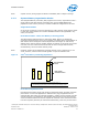

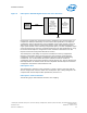
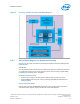
Table Of Contents
- Contents
- Revision History
- 1.0 Introduction
- 2.0 Interfaces
- 3.0 Technologies
- 3.1 Intel® Virtualization Technology (Intel® VT)
- 3.2 Intel® Trusted Execution Technology (Intel® TXT)
- 3.3 Intel® Hyper-Threading Technology (Intel® HT Technology)
- 3.4 Intel® Turbo Boost Technology 2.0
- 3.5 Intel® Advanced Vector Extensions 2.0 (Intel® AVX2)
- 3.6 Intel® Advanced Encryption Standard New Instructions (Intel® AES-NI)
- 3.7 Intel® Transactional Synchronization Extensions - New Instructions (Intel® TSX-NI)
- 3.8 Intel® 64 Architecture x2APIC
- 3.9 Power Aware Interrupt Routing (PAIR)
- 3.10 Execute Disable Bit
- 3.11 Supervisor Mode Execution Protection (SMEP)
- 4.0 Power Management
- 4.1 Advanced Configuration and Power Interface (ACPI) States Supported
- 4.2 Processor Core Power Management
- 4.3 Integrated Memory Controller (IMC) Power Management
- 4.4 PCI Express* Power Management
- 4.5 Direct Media Interface (DMI) Power Management
- 4.6 Graphics Power Management
- 5.0 Thermal Management
- 5.1 Desktop Processor Thermal Profiles
- 5.2 Thermal Metrology
- 5.3 Fan Speed Control Scheme with Digital Thermal Sensor (DTS) 1.1
- 5.4 Fan Speed Control Scheme with Digital Thermal Sensor (DTS) 2.0
- 5.5 Processor Temperature
- 5.6 Adaptive Thermal Monitor
- 5.7 THERMTRIP# Signal
- 5.8 Digital Thermal Sensor
- 5.9 Intel® Turbo Boost Technology Thermal Considerations
- 6.0 Signal Description
- 6.1 System Memory Interface Signals
- 6.2 Memory Reference and Compensation Signals
- 6.3 Reset and Miscellaneous Signals
- 6.4 PCI Express*-Based Interface Signals
- 6.5 Display Interface Signals
- 6.6 Direct Media Interface (DMI)
- 6.7 Phase Locked Loop (PLL) Signals
- 6.8 Testability Signals
- 6.9 Error and Thermal Protection Signals
- 6.10 Power Sequencing Signals
- 6.11 Processor Power Signals
- 6.12 Sense Signals
- 6.13 Ground and Non-Critical to Function (NCTF) Signals
- 6.14 Processor Internal Pull-Up / Pull-Down Terminations
- 7.0 Electrical Specifications
- 8.0 Package Mechanical Specifications
- 9.0 Processor Ball and Signal Information
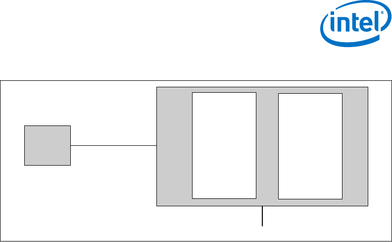
Figure 3. PCI Express* Related Register Structures in the Processor
PCI-PCI
Bridge
representing
root PCI
Express ports
(Device 1 and
Device 6)
PCI
Compatible
Host Bridge
Device
(Device 0)
PCI
Express*
Device
PEG0
DMI
PCI Express* extends the configuration space to 4096 bytes per-device/function, as
compared to 256 bytes allowed by the conventional PCI specification. PCI Express*
configuration space is divided into a PCI-compatible region (that consists of the first
256 bytes of a logical device's configuration space) and an extended PCI Express*
region (that consists of the remaining configuration space). The PCI-compatible region
can be accessed using either the mechanisms defined in the PCI specification or using
the enhanced PCI Express* configuration access mechanism described in the PCI
Express* Enhanced Configuration Mechanism section.
The PCI Express* Host Bridge is required to translate the memory-mapped PCI
Express* configuration space accesses from the host processor to PCI Express*
configuration cycles. To maintain compatibility with PCI configuration addressing
mechanisms, it is recommended that system software access the enhanced
configuration space using 32-bit operations (32-bit aligned) only. See the PCI Express
Base Specification for details of both the PCI-compatible and PCI Express* Enhanced
configuration mechanisms and transaction rules.
PCI Express* Port
The PCI Express* interface on the processor is a single, 16-lane (x16) port that can
also be configured at narrower widths. The PCI Express* port is being designed to be
compliant with the PCI Express Base Specification, Revision 3.0.
PCI Express* Lanes Connection
The following figure demonstrates the PCIe* lane mapping.
Interfaces—Processor
Desktop 4th Generation Intel
®
Core
™
Processor Family, Desktop Intel
®
Pentium
®
Processor Family, and Desktop Intel
®
Celeron
®
Processor Family
December 2013 Datasheet – Volume 1 of 2
Order No.: 328897-004 25