IA-32 Intel® Architecture Software Developer’s Manual Volume 3A: System Programming Guide, Part 1 NOTE: The IA-32 Intel Architecture Software Developer's Manual consists of five volumes: Basic Architecture, Order Number 253665; Instruction Set Reference A-M, Order Number 253666; Instruction Set Reference N-Z, Order Number 253667; System Programming Guide, Part 1, Order Number 253668; System Programming Guide, Part 2, Order Number 253669. Refer to all five volumes when evaluating your design needs.
INFORMATION IN THIS DOCUMENT IS PROVIDED IN CONNECTION WITH INTEL PRODUCTS. NO LICENSE, EXPRESS OR IMPLIED, BY ESTOPPEL OR OTHERWISE, TO ANY INTELLECTUAL PROPERTY RIGHTS IS GRANTED BY THIS DOCUMENT.
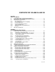
CONTENTS FOR VOLUME 3A AND 3B CHAPTER 1 ABOUT THIS MANUAL 1.1 IA-32 PROCESSORS COVERED IN THIS MANUAL . . . . . . . . . . . . . . . . . . . . . . . 1-1 1.2 OVERVIEW OF THE SYSTEM PROGRAMMING GUIDE. . . . . . . . . . . . . . . . . . . . 1-2 1.3 NOTATIONAL CONVENTIONS . . . . . . . . . . . . . . . . . . . . . . . . . . . . . . . . . . . . . . . . 1-4 1.3.1 Bit and Byte Order . . . . . . . . . . . . . . . . . . . . . . . . . . . . . . . . . . . . . . . . . . . . . . . . .1-5 1.3.
CONTENTS PAGE 2.6.7 2.6.7.1 Reading and Writing Model-Specific Registers . . . . . . . . . . . . . . . . . . . . . . . . . .2-29 Reading and Writing Model-Specific Registers in 64-Bit Mode . . . . . . . . . . .2-29 CHAPTER 3 PROTECTED-MODE MEMORY MANAGEMENT 3.1 MEMORY MANAGEMENT OVERVIEW . . . . . . . . . . . . . . . . . . . . . . . . . . . . . . . . . 3-1 3.2 USING SEGMENTS. . . . . . . . . . . . . . . . . . . . . . . . . . . . . . . . . . . . . . . . . . . . . . . . . 3-3 3.2.1 Basic Flat Model . . . .
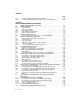
CONTENTS PAGE CHAPTER 4 PROTECTION 4.1 ENABLING AND DISABLING SEGMENT AND PAGE PROTECTION . . . . . . . . . . 4-1 4.2 FIELDS AND FLAGS USED FOR SEGMENT-LEVEL AND PAGE-LEVEL PROTECTION. . . . . . . . . . . . . . . . . . . . . . . . . . . . . . . . . . . . . . . . . . 4-2 4.2.1 Code Segment Descriptor in 64-bit Mode . . . . . . . . . . . . . . . . . . . . . . . . . . . . . . 4-4 4.3 LIMIT CHECKING . . . . . . . . . . . . . . . . . . . . . . . . . . . . . . . . . . . . . . . . . . . . . . . . . . 4-5 4.3.
CONTENTS PAGE CHAPTER 5 INTERRUPT AND EXCEPTION HANDLING 5.1 INTERRUPT AND EXCEPTION OVERVIEW . . . . . . . . . . . . . . . . . . . . . . . . . . . . . 5-1 5.2 EXCEPTION AND INTERRUPT VECTORS . . . . . . . . . . . . . . . . . . . . . . . . . . . . . . 5-2 5.3 SOURCES OF INTERRUPTS . . . . . . . . . . . . . . . . . . . . . . . . . . . . . . . . . . . . . . . . . 5-2 5.3.1 External Interrupts . . . . . . . . . . . . . . . . . . . . . . . . . . . . . . . . . . . . . . . . . . . . . . . . .5-2 5.3.
CONTENTS PAGE Interrupt 16—x87 FPU Floating-Point Error (#MF) . . . . . . . . . . . . . . . . . . . . . . Interrupt 17—Alignment Check Exception (#AC). . . . . . . . . . . . . . . . . . . . . . . . Interrupt 18—Machine-Check Exception (#MC) . . . . . . . . . . . . . . . . . . . . . . . . Interrupt 19—SIMD Floating-Point Exception (#XF) . . . . . . . . . . . . . . . . . . . . . Interrupts 32 to 255—User Defined Interrupts . . . . . . . . . . . . . . . . . . . . . . . . . .
CONTENTS PAGE 7.5.4 MP Initialization Example . . . . . . . . . . . . . . . . . . . . . . . . . . . . . . . . . . . . . . . . . .7-18 7.5.4.1 Typical BSP Initialization Sequence . . . . . . . . . . . . . . . . . . . . . . . . . . . . . . . .7-19 7.5.4.2 Typical AP Initialization Sequence . . . . . . . . . . . . . . . . . . . . . . . . . . . . . . . . .7-21 7.5.5 Identifying Logical Processors in an MP System. . . . . . . . . . . . . . . . . . . . . . . . .7-22 7.
CONTENTS PAGE 7.11.6.3 7.11.6.4 7.11.6.5 7.11.6.6 7.11.6.7 Halt Idle Logical Processors . . . . . . . . . . . . . . . . . . . . . . . . . . . . . . . . . . . . . Potential Usage of MONITOR/MWAIT in C1 Idle Loops. . . . . . . . . . . . . . . . Guidelines for Scheduling Threads on Logical Processors Sharing Execution Resources. . . . . . . . . . . . . . . . . . . . . . . . . . . . . . . . . . . . Eliminate Execution-Based Timing Loops . . . . . . . . . . . . . . . . . . . . . . . . . .
CONTENTS PAGE 8.10 8.10.1 8.11 8.11.1 8.11.2 APIC BUS MESSAGE PASSING MECHANISM AND PROTOCOL (P6 FAMILY, PENTIUM PROCESSORS). . . . . . . . . . . . . . . . . . . . . 8-42 Bus Message Formats. . . . . . . . . . . . . . . . . . . . . . . . . . . . . . . . . . . . . . . . . . . . .8-43 MESSAGE SIGNALLED INTERRUPTS . . . . . . . . . . . . . . . . . . . . . . . . . . . . . . . . 8-43 Message Address Register Format . . . . . . . . . . . . . . . . . . . . . . . . . . . . . . . . . . .
CONTENTS PAGE 9.11.6.4 9.11.6.5 9.11.7 9.11.7.1 9.11.7.2 9.11.8 9.11.8.1 9.11.8.2 9.11.8.3 9.11.8.4 9.11.8.5 9.11.8.6 9.11.8.7 9.11.8.8 9.11.8.9 Update in a System Supporting Dual-Core Technology . . . . . . . . . . . . . . . . Update Loader Enhancements . . . . . . . . . . . . . . . . . . . . . . . . . . . . . . . . . . . Update Signature and Verification . . . . . . . . . . . . . . . . . . . . . . . . . . . . . . . . . . . Determining the Signature . . . . . . . . . . . . . . . . . . . . . . . . . . . .
CONTENTS PAGE 10.11.3.1 Base and Mask Calculations with Intel EM64T. . . . . . . . . . . . . . . . . . . . . . .10-33 10.11.4 Range Size and Alignment Requirement . . . . . . . . . . . . . . . . . . . . . . . . . . . . .10-34 10.11.4.1 MTRR Precedences . . . . . . . . . . . . . . . . . . . . . . . . . . . . . . . . . . . . . . . . . . .10-34 10.11.5 MTRR Initialization . . . . . . . . . . . . . . . . . . . . . . . . . . . . . . . . . . . . . . . . . . . . . .10-35 10.11.6 Remapping Memory Types . . . . . .
CONTENTS PAGE CHAPTER 13 POWER AND THERMAL MANAGEMENT 13.1 ENHANCED INTEL SPEEDSTEP® TECHNOLOGY . . . . . . . . . . . . . . . . . . . . . . . 13.1.1 Software Interface For Initiating Performance State Transitions . . . . . . . . . . . . 13.2 THERMAL MONITORING AND PROTECTION . . . . . . . . . . . . . . . . . . . . . . . . . . . 13.2.1 Catastrophic Shutdown Detector . . . . . . . . . . . . . . . . . . . . . . . . . . . . . . . . . . . . 13.2.2 Thermal Monitor. . . . . . . . . . . . . . . . . . . . . . . . .
CONTENTS PAGE 15.2 VIRTUAL-8086 MODE . . . . . . . . . . . . . . . . . . . . . . . . . . . . . . . . . . . . . . . . . . . . . . 15-7 15.2.1 Enabling Virtual-8086 Mode . . . . . . . . . . . . . . . . . . . . . . . . . . . . . . . . . . . . . . . .15-9 15.2.2 Structure of a Virtual-8086 Task . . . . . . . . . . . . . . . . . . . . . . . . . . . . . . . . . . . . .15-9 15.2.3 Paging of Virtual-8086 Tasks . . . . . . . . . . . . . . . . . . . . . . . . . . . . . . . . . . . . . .15-10 15.2.
CONTENTS PAGE 17.6. STREAMING SIMD EXTENSIONS (SSE) . . . . . . . . . . . . . . . . . . . . . . . . . . . . . . . 17-3 17.7. STREAMING SIMD EXTENSIONS 2 (SSE2). . . . . . . . . . . . . . . . . . . . . . . . . . . . . 17-3 17.8. STREAMING SIMD EXTENSIONS 3 (SSE3). . . . . . . . . . . . . . . . . . . . . . . . . . . . . 17-3 17.9. HYPER-THREADING TECHNOLOGY. . . . . . . . . . . . . . . . . . . . . . . . . . . . . . . . . . 17-4 17.10. DUAL-CORE TECHNOLOGY . . . . . . . . . . . . . . . . . . . . . . . . . . .
CONTENTS PAGE 17.17.7.12. FXTRACT Instruction . . . . . . . . . . . . . . . . . . . . . . . . . . . . . . . . . . . . . . . . . .17-17 17.17.7.13. Load Constant Instructions . . . . . . . . . . . . . . . . . . . . . . . . . . . . . . . . . . . . . .17-17 17.17.7.14. FSETPM Instruction . . . . . . . . . . . . . . . . . . . . . . . . . . . . . . . . . . . . . . . . . . .17-17 17.17.7.15. FXAM Instruction . . . . . . . . . . . . . . . . . . . . . . . . . . . . . . . . . . . . . . . . . . . . .17-18 17.17.7.
CONTENTS PAGE 17.29.1. 17.29.2. 17.29.3. 17.30. 17.30.1. 17.30.2. 17.30.3. 17.30.4. 17.31. 17.32. 17.32.1. 17.33. 17.34. 17.35. 17.36. 17.36.1. 17.36.2. 17.36.3. 17.36.4. 17.36.5. 17.37. Large Pages . . . . . . . . . . . . . . . . . . . . . . . . . . . . . . . . . . . . . . . . . . . . . . . . . . PCD and PWT Flags . . . . . . . . . . . . . . . . . . . . . . . . . . . . . . . . . . . . . . . . . . . . Enabling and Disabling Paging . . . . . . . . . . . . . . . . . . . . . . . . . . . . . . . . . . . .
CONTENTS PAGE 18.5.7.1 Last Exception Records and Intel EM64T . . . . . . . . . . . . . . . . . . . . . . . . . .18-19 18.5.8 Branch Trace Store (BTS) . . . . . . . . . . . . . . . . . . . . . . . . . . . . . . . . . . . . . . . . .18-19 18.5.8.1 Detection of the BTS Facilities . . . . . . . . . . . . . . . . . . . . . . . . . . . . . . . . . . .18-20 18.5.8.2 Setting Up the DS Save Area . . . . . . . . . . . . . . . . . . . . . . . . . . . . . . . . . . . .18-20 18.5.8.3 Setting Up the BTS Buffer . . . .
CONTENTS PAGE 18.11 18.11.1 18.11.2 18.11.3 18.11.4 18.12 18.13 18.14 18.14.1 18.14.2 18.14.3 18.14.4 18.14.5 18.15 18.15.1 18.15.2 18.15.3 PERFORMANCE MONITORING AND HYPER-THREADING TECHNOLOGY . . . . . . . . . . . . . . . . . . . . . . . . . . . . . . . . . . . . . . . . . . . . . . . . . . ESCR MSRs . . . . . . . . . . . . . . . . . . . . . . . . . . . . . . . . . . . . . . . . . . . . . . . . . . CCCR MSRs . . . . . . . . . . . . . . . . . . . . . . . . . . . . . . . . . . . . . . . . . . . . . . . .
CONTENTS PAGE 20.7 20.7.1 20.7.2 20.8 20.8.1 20.8.2 20.8.3 20.9 20.9.1 20.9.2 20.9.3 20.9.4 20.9.5 20.10 20.10.1 20.10.2 20.10.3 20.10.4 20.11 VM-EXIT CONTROL FIELDS. . . . . . . . . . . . . . . . . . . . . . . . . . . . . . . . . . . . . . . . 20-14 VM-Exit Controls . . . . . . . . . . . . . . . . . . . . . . . . . . . . . . . . . . . . . . . . . . . . . . . .20-14 VM-Exit Controls for MSRs . . . . . . . . . . . . . . . . . . . . . . . . . . . . . . . . . . . . . . . .20-15 VM-ENTRY CONTROL FIELDS . . .
CONTENTS PAGE 22.3.2.1 22.3.2.2 Loading Guest Control Registers, Debug Registers, and MSRs . . . . . . . . Loading Guest Segment Registers and Descriptor-Table Registers . . . . . . . . . . . . . . . . . . . . . . . . . . . . . . . . . . . . . . . . . . . . . . . . . . . 22.3.2.3 Loading Guest RIP, RSP, and RFLAGS . . . . . . . . . . . . . . . . . . . . . . . . . . . 22.3.2.4 Loading Page-Directory Pointers . . . . . . . . . . . . . . . . . . . . . . . . . . . . . . . . 22.3.
CONTENTS PAGE 24.3.2 24.4 24.4.1 24.4.1.1 24.4.2 24.5 24.6 24.7 Exiting From SMM . . . . . . . . . . . . . . . . . . . . . . . . . . . . . . . . . . . . . . . . . . . . . . . .26-4 SMRAM . . . . . . . . . . . . . . . . . . . . . . . . . . . . . . . . . . . . . . . . . . . . . . . . . . . . . . . . . 26-4 SMRAM State Save Map. . . . . . . . . . . . . . . . . . . . . . . . . . . . . . . . . . . . . . . . . . .26-5 SMRAM State Save Map and Intel EM64T . . . . . . . . . . . . . . . . . . . . . . . . . .
CONTENTS PAGE CHAPTER 25 VIRTUAL-MACHINE MONITOR PROGRAMMING CONSIDERATIONS 25.1 VMX SYSTEM PROGRAMMING OVERVIEW. . . . . . . . . . . . . . . . . . . . . . . . . . . . 23-1 25.2 SUPPORTING PROCESSOR OPERATING MODES IN GUEST ENVIRONMENTS. . . . . . . . . . . . . . . . . . . . . . . . . . . . . . . . . . . . . . . . . . . . . . . . . . 23-1 25.2.1 Emulating Guest Execution . . . . . . . . . . . . . . . . . . . . . . . . . . . . . . . . . . . . . . . . 23-2 25.3 MANAGING VMCS REGIONS AND POINTERS . . . . . .
CONTENTS PAGE 26.3.5.1 Initialization of Virtual TLB . . . . . . . . . . . . . . . . . . . . . . . . . . . . . . . . . . . . . . .24-6 26.3.5.2 Response to Page Faults . . . . . . . . . . . . . . . . . . . . . . . . . . . . . . . . . . . . . . . .24-7 26.3.5.3 Response to Uses of INVLPG . . . . . . . . . . . . . . . . . . . . . . . . . . . . . . . . . . . .24-9 26.3.5.4 Response to CR3 Writes . . . . . . . . . . . . . . . . . . . . . . . . . . . . . . . . . . . . . . .24-10 26.4 MICROCODE UPDATE FACILITY.
CONTENTS PAGE APPENDIX C MP INITIALIZATION FOR P6 FAMILY PROCESSORS C.1 OVERVIEW OF THE MP INITIALIZATION PROCESS FOR P6 FAMILY PROCESSORS . . . . . . . . . . . . . . . . . . . . . . . . . . . . . . . . . . . . . . . . . . . . . . . . . . . . C-1 C.2 MP INITIALIZATION PROTOCOL ALGORITHM . . . . . . . . . . . . . . . . . . . . . . . . . . . C-2 C.2.1 Error Detection and Handling During the MP Initialization Protocol. . . . . . . . . . . C-4 APPENDIX D PROGRAMMING THE LINT0 AND LINT1 INPUTS D.1 CONSTANTS . .
CONTENTS PAGE H.3.4 H.4 H.4.1 H.4.2 H.4.3 H.4.4 32-Bit Host-State Field . . . . . . . . . . . . . . . . . . . . . . . . . . . . . . . . . . . . . . . . . . . . NATURAL-WIDTH FIELDS . . . . . . . . . . . . . . . . . . . . . . . . . . . . . . . . . . . . . . . . . . . Natural-Width Control Fields . . . . . . . . . . . . . . . . . . . . . . . . . . . . . . . . . . . . . . . . Natural-Width Read-Only Data Fields . . . . . . . . . . . . . . . . . . . . . . . . . . . . . . . . .
CONTENTS PAGE Figure 3-23. Figure 3-24. Figure 3-25. Figure 3-26. Figure 3-27. Figure 3-28. Figure 4-1. Figure 4-2. Figure 4-3. Figure 4-4. Figure 4-5. Figure 4-6. Figure 4-7. Figure 4-8. Figure 4-9. Figure 4-10. Figure 4-11. Figure 4-12. Figure 4-13. Figure 4-14. Figure 4-15. Figure 5-1. Figure 5-2. Figure 5-3. Figure 5-4. Figure 5-5. Figure 5-6. Figure 5-7. Figure 5-8. Figure 5-9. Figure 6-1. Figure 6-2. Figure 6-3. Figure 6-4. Figure 6-5. Figure 6-6. Figure 6-7. Figure 6-8. Figure 6-9. Figure 6-10.
CONTENTS PAGE Figure 7-6. Figure 8-1. Figure 8-2. Figure 8-3. Figure 8-4. Figure 8-5. Figure 8-6. Figure 8-7. Figure 8-8. Figure 8-9. Figure 8-10. Figure 8-11. Figure 8-12. Figure 8-13. Figure 8-14. Figure 8-15. Figure 8-16. Figure 8-17. Figure 8-18. Figure 8-19. Figure 8-20. Figure 8-21. Figure 8-22. Figure 8-23. Figure 8-24. Figure 8-25. Figure 9-1. Figure 9-2. Figure 9-3. Figure 9-4. Figure 9-5. Figure 9-6. Figure 9-7. Figure 9-8. Figure 9-9. Figure 10-1. Figure 10-2. Figure 10-3. Figure 10-4.
CONTENTS PAGE Figure 11-2. Figure 12-1. Figure 13-1. Figure 13-2. Figure 13-3. Figure 13-4. Figure 13-5. Figure 13-6. Figure 14-1. Figure 14-2. Figure 14-3. Figure 14-4. Figure 14-5. Figure 14-6. Figure 14-7. Figure 15-1. Figure 15-2. Figure 15-3. Figure 15-4. Figure 15-5. Figure 16-1. Figure 17-1. Figure 18-1. Figure 18-2. Figure 18-3. Figure 18-4. Figure 18-5. Figure 18-6. Figure 18-7. Figure 18-8. Figure 18-9. Figure 18-10. Figure 18-11. Figure 18-12. Figure 18-13. Figure 18-14. Figure 18-15.
CONTENTS PAGE Figure 18-23. MSR_IFSB_CTL6, Address: 107D2H; MSR_IFSB_CNTR7, Address: 107D3H . . . . . . . . . . . . . . . . . . . . . . . . . . . .18-70 Figure 18-24. PerfEvtSel0 and PerfEvtSel1 MSRs . . . . . . . . . . . . . . . . . . . . . . . . . . . . . . .18-71 Figure 18-25. CESR MSR (Pentium Processor Only). . . . . . . . . . . . . . . . . . . . . . . . . . . . .18-75 Figure 19-1. Interaction of a Virtual-Machine Monitor and Guests . . . . . . . . . . . . . . . . . . .14-3 Figure 19-1.
CONTENTS PAGE Table 6-1. Table 6-2. Table 7-1. Table 7-2. Table 8-1. Table 8-2. Table 8-3. Table 8-4. Table 9-1. Table 9-2. Table 9-3. Table 9-4. Table 9-5. Table 9-6. Table 9-7. Table 9-8. Table 9-9. Table 9-10. Table 9-11. Table 9-12. Table 9-13. Table 9-14. Table 9-15. Table 9-16. Table 9-17. Table 9-18. Table 10-1. Table 10-2. Table 10-3. Table 10-4. Table 10-5. Table 10-6. Table 10-7. Table 10-8. Table 10-9. Table 10-10. Table 10-11. Table 10-12. Table 11-1. Table 11-2.
CONTENTS PAGE Table 11-3. Table 12-1. Table 13-1. Table 14-1. Table 14-2. Table 14-3. Table 14-4. Table 14-5. Table 14-6. Table 14-7. Table 14-8. Table 15-1. Table 15-2. Table 16-1. Table 17-1. Table 17-2. Table 17-3. Table 18-1. Table 18-2. Table 18-3. Table 18-4. Table 18-5. Table 18-6. Table 18-7. Table 18-8. Table 18-9. Table 18-10. Table 20-1. Table 20-2. Table 20-3. Table 20-4. Table 20-5. Table 20-6. Table 20-7. Table 20-8. Table 20-9. Table 20-10. Table 20-11. Table 20-12. Table 20-13. Table 20-14.
CONTENTS PAGE Table 23-1. Table 23-2. Table 23-3. Table 23-4. Table 23-5. Table 24-1. Table 24-2. Table 24-3. Table 24-4. Table 24-5. Table 24-6. Table 24-7. Table 24-6. Table 24-7. Table 25-1. Table A-1. Table A-2. Table A-3. Table A-4. Table A-5. Table A-6. Table A-7. Table A-8. Table A-9. Table A-10. Table A-11. Table B-1. Table B-2. Table B-3. Table B-4. Table B-5. Table B-6. Table C-1. Table E-1. Table E-2. Table E-3. Table F-1. Table F-2. Exit Qualification for Debug Exceptions . . . . . . . . . . .
CONTENTS PAGE Table F-3. Table F-4. Table G-1. Table H-1. Table H-2. Table H-3. Table H-4. Table H-5. Table H-6. Table H-7. Table H-8. Table H-9. Table H-10. Table H-11. Table H-12. Table I-1. Table J-1. xxxiv Vol. 3A Non-Focused Lowest Priority Message (34 Cycles). . . . . . . . . . . . . . . . . . . . .F-3 APIC Bus Status Cycles Interpretation . . . . . . . . . . . . . . . . . . . . . . . . . . . . . . .F-5 Memory Types Used For VMCS Access . . . . . . . . . . . . . . . . . . . . . . . . . . . .
1 About This Manual
CHAPTER 1 ABOUT THIS MANUAL The IA-32 Intel® Architecture Software Developer’s Manual, Volume 3A: System Programming Guide, Part 1 (order number 253668) and the IA-32 Intel® Architecture Software Developer’s Manual, Volume 3B: System Programming Guide, Part 2 (order number 253669) are part of a set that describes the architecture and programming environment of all IA-32 Intel Architecture processors.
ABOUT THIS MANUAL 1.2 OVERVIEW OF THE SYSTEM PROGRAMMING GUIDE A description of this manual’s content follows: Chapter 1 — About This Manual. Gives an overview of all three volumes of the IA-32 Intel Architecture Software Developer’s Manual. It also describes the notational conventions in these manuals and lists related Intel manuals and documentation of interest to programmers and hardware designers. Chapter 2 — System Architecture Overview.
ABOUT THIS MANUAL level, including: task switching, exception handling, and compatibility with existing system environments. Chapter 12 — SSE, SSE2 and SSE3 System Programming. Describes those aspects of SSE/SSE2/SSE3 extensions that must be handled and considered at the system programming level, including task switching, exception handling, and compatibility with existing system environments. Chapter 13 — Power and Thermal Management.
ABOUT THIS MANUAL Chapter 25 — Virtual-Machine Monitoring Programming Considerations. Describes programming considerations for VMMs. VMMs manage virtual machines (VMs). Chapter 26 — Virtualization of System Resources. Describes the virtualization of the system resources. These include: debugging facilities, address translation, physical memory, and microcode update facilities. Chapter 27 — Handling Boundary Conditions in a Virtual Machine Monitor.
ABOUT THIS MANUAL 1.3.1 Bit and Byte Order In illustrations of data structures in memory, smaller addresses appear toward the bottom of the figure; addresses increase toward the top. Bit positions are numbered from right to left. The numerical value of a set bit is equal to two raised to the power of the bit position. IA-32 processors are “little endian” machines; this means the bytes of a word are numbered starting from the least significant byte. Figure 1-1 illustrates these conventions. 1.3.
ABOUT THIS MANUAL Highest 31 Address Data Structure 8 7 24 23 16 15 Byte 3 Byte 2 Byte 1 Bit offset 0 Byte 0 28 24 20 16 12 8 4 0 Lowest Address Byte Offset Figure 1-1. Bit and Byte Order 1.3.3 Instruction Operands When instructions are represented symbolically, a subset of the IA-32 assembly language is used. In this subset, an instruction has the following format: label: mnemonic argument1, argument2, argument3 where: • • A label is an identifier which is followed by a colon.
ABOUT THIS MANUAL 1.3.4 Hexadecimal and Binary Numbers Base 16 (hexadecimal) numbers are represented by a string of hexadecimal digits followed by the character H (for example, F82EH). A hexadecimal digit is a character from the following set: 0, 1, 2, 3, 4, 5, 6, 7, 8, 9, A, B, C, D, E, and F. Base 2 (binary) numbers are represented by a string of 1s and 0s, sometimes followed by the character B (for example, 1010B).
ABOUT THIS MANUAL CPUID Input and Output CPUID.01H:ECX.SSE [bit 25] = 1 Input value for EAX register Output register and feature flag or field name with bit position(s) Value (or range) of output Control Register Values CR4.OSFXSR[bit 9] = 1 Example CR name Feature flag or field name with bit position(s) Value (or range) of output Model-Specific Register Values IA32_MISC_ENABLES.
ABOUT THIS MANUAL be able to report an accurate code. In this case, the error code is zero, as shown below for a general-protection exception. #GP(0) 1.4 RELATED LITERATURE Literature related to IA-32 processors is listed on-line at this link: http://developer.intel.com/design/processor/ Some of the documents listed at this web site can be viewed on-line; others can be ordered.
ABOUT THIS MANUAL 1-10 Vol.
2 System Architecture Overview
CHAPTER 2 SYSTEM ARCHITECTURE OVERVIEW IA-32 architecture (beginning with the Intel386 processor family) provides extensive support for operating-system and system-development software. This support offers multiple modes of operation, which include: • Real mode, protected mode, virtual 8086 mode, and system management mode. These are sometimes referred to as legacy modes. • IA-32e mode (added by Intel® Extended Memory 64 Technology).
SYSTEM ARCHITECTURE OVERVIEW 2.1 OVERVIEW OF THE SYSTEM-LEVEL ARCHITECTURE IA-32 system-level architecture consists of a set of registers, data structures, and instructions designed to support basic system-level operations such as memory management, interrupt and exception handling, task management, and control of multiple processors. Figure 2-1 provides a summary of system registers and data structures that applies to 32-bit modes.
SYSTEM ARCHITECTURE OVERVIEW Physical Address EFLAGS Register Control Registers CR4 CR3 CR2 CR1 CR0 Task Register Interrupt Vector Code, Data or Stack Segment Linear Address Task-State Segment (TSS) Segment Selector Register Global Descriptor Table (GDT) Segment Sel. Seg. Desc. TSS Seg. Sel. TSS Desc. Interrupt Handler Code Current Stack TSS Seg. Desc. Interrupt Descriptor Table (IDT) Task-State Segment (TSS) TSS Desc. Interrupt Gate Task Code Data Stack LDT Desc.
SYSTEM ARCHITECTURE OVERVIEW RFLAGS Physical Address Control Register CR8 CR4 CR3 CR2 CR1 CR0 Task Register Interrupt Vector Code, Data or Stack Segment (Base =0) Linear Address Task-State Segment (TSS) Segment Selector Register Global Descriptor Table (GDT) Segment Sel. Seg. Desc. TR TSS Desc. NULL Seg. Desc. Interrupt Descriptor Table (IDT) Interr. Handler Seg. Desc. Interrupt Gate LDT Desc. GDTR Trap Gate IST Local Descriptor Table (LDT) NULL Call-Gate Segment Selector Seg. Desc.
SYSTEM ARCHITECTURE OVERVIEW 2.1.1 Global and Local Descriptor Tables When operating in protected mode, all memory accesses pass through either the global descriptor table (GDT) or an optional local descriptor table (LDT) as shown in Figure 2-1. These tables contain entries called segment descriptors. Segment descriptors provide the base address of segments well as access rights, type, and usage information. Each segment descriptor has an associated segment selector.
SYSTEM ARCHITECTURE OVERVIEW For example, a CALL to a call gate can provide access to a procedure in a code segment that is at the same or a numerically lower privilege level (more privileged) than the current code segment. To access a procedure through a call gate, the calling procedure1 supplies the selector for the call gate.
SYSTEM ARCHITECTURE OVERVIEW A task can also be accessed through a task gate. A task gate is similar to a call gate, except that it provides access (through a segment selector) to a TSS rather than a code segment. 2.1.3.1 Task-State Segments in IA-32e Mode Hardware task switches are not supported in IA-32e mode. However, TSSs continue to exist. The base address of a TSS is specified by its descriptor.
SYSTEM ARCHITECTURE OVERVIEW The location of pages (sometimes called page frames) in physical memory is contained in two types of system data structures: page directories and page tables. Both structures reside in physical memory (see Figure 2-1). The base physical address of the page directory is contained in control register CR3. An entry in a page directory contains the physical address of the base of a page table, access rights and memory management information.
SYSTEM ARCHITECTURE OVERVIEW • The GDTR, LDTR, and IDTR registers contain the linear addresses and sizes (limits) of their respective tables. See also: Section 2.4, “Memory-Management Registers.” • The task register contains the linear address and size of the TSS for the current task. See also: Section 2.4, “Memory-Management Registers.” • Model-specific registers (not shown in Figure 2-1).
SYSTEM ARCHITECTURE OVERVIEW 2.1.7 Other System Resources Besides the system registers and data structures described in the previous sections, system architecture provides the following additional resources: • • • Operating system instructions (see also: Section 2.6, “System Instruction Summary”). Performance-monitoring counters (not shown in Figure 2-1). Internal caches and buffers (not shown in Figure 2-1).
SYSTEM ARCHITECTURE OVERVIEW SMI# Real-Address Mode Reset or PE=0 PE=1 Reset or RSM SMI# Reset Protected Mode See** VM=0 RSM LME=1, CR0.PG=1* SMI# IA-32e Mode RSM System Management Mode VM=1 * See Section 9.8.5 Virtual-8086 Mode SMI# ** See Section 9.8.5.4 RSM Figure 2-3. Transitions Among the Processor’s Operating Modes The processor is placed in real-address mode following power-up or a reset.
SYSTEM ARCHITECTURE OVERVIEW 2.3 SYSTEM FLAGS AND FIELDS IN THE EFLAGS REGISTER The system flags and IOPL field of the EFLAGS register control I/O, maskable hardware interrupts, debugging, task switching, and the virtual-8086 mode (see Figure 2-4). Only privileged code (typically operating system or executive code) should be allowed to modify these bits. The system flags and IOPL are: TF Trap (bit 8) — Set to enable single-step mode for debugging; clear to disable singlestep mode.
SYSTEM ARCHITECTURE OVERVIEW The IOPL is also one of the mechanisms that controls the modification of the IF flag and the handling of interrupts in virtual-8086 mode when virtual mode extensions are in effect (when CR4.VME = 1). See also: Chapter 13, “Input/Output,” in the IA-32 Intel® Architecture Software Developer’s Manual, Volume 1. NT Nested task (bit 14) — Controls the chaining of interrupted and called tasks.
SYSTEM ARCHITECTURE OVERVIEW VIF Virtual Interrupt (bit 19) — Contains a virtual image of the IF flag. This flag is used in conjunction with the VIP flag. The processor only recognizes the VIF flag when either the VME flag or the PVI flag in control register CR4 is set and the IOPL is less than 3. (The VME flag enables the virtual-8086 mode extensions; the PVI flag enables the protected-mode virtual interrupts.) See also: Section 15.3.3.5, “Method 6: Software Interrupt Handling,” and Section 15.
SYSTEM ARCHITECTURE OVERVIEW 47(79) System Table Registers 16 15 0 GDTR 32(64)-bit Linear Base Address 16-Bit Table Limit IDTR 32(64)-bit Linear Base Address 16-Bit Table Limit System Segment Registers 15 0 Task Register LDTR Segment Descriptor Registers (Automatically Loaded) Attributes Seg. Sel. 32(64)-bit Linear Base Address Segment Limit Seg. Sel. 32(64)-bit Linear Base Address Segment Limit Figure 2-5. Memory Management Registers 2.4.
SYSTEM ARCHITECTURE OVERVIEW 2.4.3 IDTR Interrupt Descriptor Table Register The IDTR register holds the base address (32 bits in protected mode; 64 bits in IA-32e mode) and 16-bit table limit for the IDT. The base address specifies the linear address of byte 0 of the IDT; the table limit specifies the number of bytes in the table. The LIDT and SIDT instructions load and store the IDTR register, respectively.
SYSTEM ARCHITECTURE OVERVIEW The control registers are summarized below, and each architecturally defined control field in these control registers are described individually. In Figure 2-6, the width of the register in 64-bit mode is indicated in parenthesis (except for CR0). • CR0 — Contains system control flags that control operating mode and states of the processor. • • • CR1 — Reserved. CR2 — Contains the page-fault linear address (the linear address that caused a page fault).
SYSTEM ARCHITECTURE OVERVIEW 31(63) 10 9 8 7 6 5 4 3 2 1 0 T P V P P M P P C G C A S D S V M E D I E E E E E E Reserved (set to 0) CR4 OSXMMEXCPT OSFXSR 31(63) 12 11 5 4 3 2 0 P P C W D T Page-Directory Base 31(63) CR3 (PDBR) 0 Page-Fault Linear Address 31(63) CR2 0 CR1 31 30 29 28 P C N G D W 19 18 17 16 15 A M W P 6 5 4 3 2 1 0 N E T E M P E T S M P E CR0 Reserved Figure 2-6.
SYSTEM ARCHITECTURE OVERVIEW NW Not Write-through (bit 29 of CR0) — When the NW and CD flags are clear, writeback (for Pentium 4, Intel Xeon, P6 family, and Pentium processors) or write-through (for Intel486 processors) is enabled for writes that hit the cache and invalidation cycles are enabled. See Table 10-5 for detailed information about the affect of the NW flag on caching for other settings of the CD and NW flags.
SYSTEM ARCHITECTURE OVERVIEW • If the TS flag is set and the MP flag (bit 1 of CR0) and EM flag are clear, an #NM exception is not raised prior to the execution of an x87 FPU WAIT/FWAIT instruction. • If the EM flag is set, the setting of the TS flag has no affect on the execution of x87 FPU/MMX/SSE/SSE2/SSE3 instructions. Table 2-1 shows the actions taken when the processor encounters an x87 FPU instruction based on the settings of the TS, EM, and MP flags.
SYSTEM ARCHITECTURE OVERVIEW FPU or math coprocessor present in the system. Table 2-1 shows the interaction of the EM, MP, and TS flags. Also, when the EM flag is set, execution of an MMX instruction causes an invalidopcode exception (#UD) to be generated (see Table 11-1). Thus, if an IA-32 processor incorporates MMX technology, the EM flag must be set to 0 to enable execution of MMX instructions.
SYSTEM ARCHITECTURE OVERVIEW VME Virtual-8086 Mode Extensions (bit 0 of CR4) — Enables interrupt- and exceptionhandling extensions in virtual-8086 mode when set; disables the extensions when clear.
SYSTEM ARCHITECTURE OVERVIEW When enabling the global page feature, paging must be enabled (by setting the PG flag in control register CR0) before the PGE flag is set. Reversing this sequence may affect program correctness, and processor performance will be impacted. See also: Section 3.12, “Translation Lookaside Buffers (TLBs).
SYSTEM ARCHITECTURE OVERVIEW 2.5.1 CPUID Qualification of Control Register Flags The VME, PVI, TSD, DE, PSE, PAE, MCE, PGE, PCE, OSFXSR, and OSXMMEXCPT flags in control register CR4 are model specific. All of these flags (except the PCE flag) can be qualified with the CPUID instruction to determine if they are implemented on the processor before they are used. The CR8 register is available on processors that support Intel EM64T. Support for Intel EM64T can determined using CPUID. 2.
SYSTEM ARCHITECTURE OVERVIEW Table 2-2. Summary of System Instructions (Contd.
SYSTEM ARCHITECTURE OVERVIEW • SLDT (Store LDT Register) — Stores the LDT segment selector from the LDTR register into memory or a general-purpose register. • LTR (Load Task Register) — Loads segment selector and segment descriptor for a TSS from memory into the task register. (The segment selector operand can also be located in a general-purpose register.
SYSTEM ARCHITECTURE OVERVIEW Offset Is Within Limits (LSL Instruction),” for a detailed explanation of the function and use of this instruction. The VERR (verify for reading) and VERW (verify for writing) instructions verify if a selected segment is readable or writable, respectively, at a given CPL. See Section 4.10.2, “Checking Read/Write Rights (VERR and VERW Instructions),” for a detailed explanation of the function and use of this instruction. 2.6.
SYSTEM ARCHITECTURE OVERVIEW Hardware may respond to this signal in a number of ways. An indicator light on the front panel may be turned on. An NMI interrupt for recording diagnostic information may be generated. Reset initialization may be invoked (note that the BINIT# pin was introduced with the Pentium Pro processor). If any non-wake events are pending during shutdown, they will be handled after the wake event from shutdown is processed (for example, A20M# interrupts).
SYSTEM ARCHITECTURE OVERVIEW See Section 18.10, “Performance Monitoring Overview,” and Section 18.9, “Time-Stamp Counter,” for more information about the performance monitoring and time-stamp counters. The RDTSC instruction was introduced into the IA-32 architecture with the Pentium processor. The RDPMC instruction was introduced into the IA-32 architecture with the Pentium Pro processor and the Pentium processor with MMX technology.
SYSTEM ARCHITECTURE OVERVIEW 2-30 Vol.
3 Protected-Mode Memory Management
CHAPTER 3 PROTECTED-MODE MEMORY MANAGEMENT This chapter describes the IA-32 architecture’s protected-mode memory management facilities, including the physical memory requirements, segmentation mechanism, and paging mechanism. See also: Chapter 4, “Protection” (for a description of the processor’s protection mechanism) and Chapter 15, “8086 Emulation” (for a description of memory addressing protection in realaddress and virtual-8086 modes). 3.
PROTECTED-MODE MEMORY MANAGEMENT Logical Address (or Far Pointer) Segment Selector Offset Linear Address Space Global Descriptor Table (GDT) Dir Linear Address Table Offset Segment Page Table Segment Descriptor Page Directory Lin. Addr. Physical Address Space Page Phy. Addr. Entry Entry Segment Base Address Page Segmentation Paging Figure 3-1.
PROTECTED-MODE MEMORY MANAGEMENT If the page being accessed is not currently in physical memory, the processor interrupts execution of the program (by generating a page-fault exception). The operating system or executive then reads the page into physical memory from the disk and continues executing the program. When paging is implemented properly in the operating-system or executive, the swapping of pages between physical memory and the disk is transparent to the correct execution of a program.
PROTECTED-MODE MEMORY MANAGEMENT Linear Address Space (or Physical Memory) Segment Registers CS Code Code- and Data-Segment Descriptors Not Present SS DS ES FFFFFFFFH Access Limit Base Address Data and Stack 0 FS GS Figure 3-2. Flat Model Segment Registers Segment Descriptors Linear Address Space (or Physical Memory) Access Limit Base Address Code FFFFFFFFH CS Not Present ES SS DS FS Memory I/O Access Limit Base Address Data and Stack GS 0 Figure 3-3.
PROTECTED-MODE MEMORY MANAGEMENT 3.2.3 Multi-Segment Model A multi-segment model (such as the one shown in Figure 3-4) uses the full capabilities of the segmentation mechanism to provided hardware enforced protection of code, data structures, and programs and tasks. Here, each program (or task) is given its own table of segment descriptors and its own segments. The segments can be completely private to their assigned programs or shared among programs.
PROTECTED-MODE MEMORY MANAGEMENT 3.2.4 Segmentation in IA-32e Mode In IA-32e mode, the effects of segmentation depend on whether the processor is running in compatibility mode or 64-bit mode. In compatibility mode, segmentation functions just as it does using legacy 16-bit or 32-bit protected mode semantics. In 64-bit mode, segmentation is generally (but not completely) disabled, creating a flat 64-bit linear-address space.
PROTECTED-MODE MEMORY MANAGEMENT 3.3.1 Physical Address Space for Processors with Intel® EM64T On processors that support Intel EM64T (CPUID.80000001.EDX[29] = 1), the size of physical address range is implementation-specific and indicated by CPUID.80000001H. The physical address size supported by a given implementation is available to IA-32e mode and enhanced legacy PAE paging. See also: Section 3.8.1, “Enhanced Legacy PAE Paging”. 3.
PROTECTED-MODE MEMORY MANAGEMENT Logical Address 0 31(63) Offset (Effective Address) 15 0 Seg. Selector Descriptor Table Segment Descriptor Base Address + 31(63) 0 Linear Address Figure 3-5. Logical Address to Linear Address Translation If paging is not used, the processor maps the linear address directly to a physical address (that is, the linear address goes out on the processor’s address bus).
PROTECTED-MODE MEMORY MANAGEMENT TI (table indicator) flag (Bit 2) — Specifies the descriptor table to use: clearing this flag selects the GDT; setting this flag selects the current LDT. 15 3 2 1 0 Index T RPL I Table Indicator 0 = GDT 1 = LDT Requested Privilege Level (RPL) Figure 3-6. Segment Selector Requested Privilege Level (RPL) (Bits 0 and 1) — Specifies the privilege level of the selector. The privilege level can range from 0 to 3, with 0 being the most privileged level. See Section 4.
PROTECTED-MODE MEMORY MANAGEMENT can be available for immediate use. Other segments can be made available by loading their segment selectors into these registers during program execution. Visible Part Segment Selector Hidden Part Base Address, Limit, Access Information CS SS DS ES FS GS Figure 3-7. Segment Registers Every segment register has a “visible” part and a “hidden” part. (The hidden part is sometimes referred to as a “descriptor cache” or a “shadow register.
PROTECTED-MODE MEMORY MANAGEMENT 3.4.4 Segment Loading Instructions in IA-32e Mode Because ES, DS, and SS segment registers are not used in 64-bit mode, their fields (base, limit, and attribute) in segment descriptor registers are ignored. Some forms of segment load instructions are also invalid (for example, LDS, POP ES). Address calculations that reference the ES, DS, or SS segments are treated as if the segment base is zero.
PROTECTED-MODE MEMORY MANAGEMENT 3.4.5 Segment Descriptors A segment descriptor is a data structure in a GDT or LDT that provides the processor with the size and location of a segment, as well as access control and status information. Segment descriptors are typically created by compilers, linkers, loaders, or the operating system or executive, but not application programs. Figure 3-8 illustrates the general descriptor format for all types of segment descriptors.
PROTECTED-MODE MEMORY MANAGEMENT segment limit has the reverse function; the offset can range from the segment limit to FFFFFFFFH or FFFFH, depending on the setting of the B flag. Offsets less than the segment limit generate general-protection exceptions. Decreasing the value in the segment limit field for an expand-down segment allocates new memory at the bottom of the segment's address space, rather than at the top.
PROTECTED-MODE MEMORY MANAGEMENT segment. (This flag should always be set to 1 for 32-bit code and data segments and to 0 for 16-bit code and data segments.) • Executable code segment. The flag is called the D flag and it indicates the default length for effective addresses and operands referenced by instructions in the segment. If the flag is set, 32-bit addresses and 32-bit or 8-bit operands are assumed; if it is clear, 16-bit addresses and 16-bit or 8-bit operands are assumed.
PROTECTED-MODE MEMORY MANAGEMENT L (64-bit code segment) flag In IA-32e mode, bit 21 of the second doubleword of the segment descriptor indicates whether a code segment contains native 64-bit code. A value of 1 indicates instructions in this code segment are executed in 64-bit mode. A value of 0 indicates the instructions in this code segment are executed in compatibility mode. If L-bit is set, then D-bit must be cleared.
PROTECTED-MODE MEMORY MANAGEMENT Stack segments are data segments which must be read/write segments. Loading the SS register with a segment selector for a nonwritable data segment generates a general-protection exception (#GP). If the size of a stack segment needs to be changed dynamically, the stack segment can be an expand-down data segment (expansion-direction flag set). Here, dynamically changing the segment limit causes stack space to be added to the bottom of the stack.
PROTECTED-MODE MEMORY MANAGEMENT 3.5 SYSTEM DESCRIPTOR TYPES When the S (descriptor type) flag in a segment descriptor is clear, the descriptor type is a system descriptor. The processor recognizes the following types of system descriptors: • • • • • • Local descriptor-table (LDT) segment descriptor. Task-state segment (TSS) descriptor. Call-gate descriptor. Interrupt-gate descriptor. Trap-gate descriptor. Task-gate descriptor.
PROTECTED-MODE MEMORY MANAGEMENT See also: Section 3.5.1, “Segment Descriptor Tables”, and Section 6.2.2, “TSS Descriptor” (for more information on the system-segment descriptors); see Section 4.8.3, “Call Gates”, Section 5.11, “IDT Descriptors”, and Section 6.2.5, “Task-Gate Descriptor” (for more information on the gate descriptors). 3.5.1 Segment Descriptor Tables A segment descriptor table is an array of segment descriptors (see Figure 3-10).
PROTECTED-MODE MEMORY MANAGEMENT Each system must have one GDT defined, which may be used for all programs and tasks in the system. Optionally, one or more LDTs can be defined. For example, an LDT can be defined for each separate task being run, or some or all tasks can share the same LDT. The GDT is not a segment itself; instead, it is a data structure in linear address space. The base linear address and limit of the GDT must be loaded into the GDTR register (see Section 2.
PROTECTED-MODE MEMORY MANAGEMENT 3.5.2 Segment Descriptor Tables in IA-32e Mode In IA-32e mode, a segment descriptor table can contain up to 8192 (213) 8-byte descriptors. An entry in the segment descriptor table can be 8 bytes. System descriptors are expanded to 16 bytes (occupying the space of two entries). GDTR and LDTR registers are expanded to hold 64-bit base address. The corresponding pseudo-descriptor is 80 bits. (see the bottom diagram in Figure 3-11).
PROTECTED-MODE MEMORY MANAGEMENT accessed for a long time. See Section 3.12, “Translation Lookaside Buffers (TLBs)”, for more information on the TLBs. 3.6.1 Paging Options Paging is controlled by three flags in the processor’s control registers: • PG (paging) flag. Bit 31 of CR0 (available in all IA-32 processors beginning with the Intel386 processor). • • PSE (page size extensions) flag. Bit 4 of CR4 (introduced in the Pentium processor). PAE (physical address extension) flag.
PROTECTED-MODE MEMORY MANAGEMENT 3.6.2 Page Tables and Directories in the Absence of Intel EM64T The information that the processor uses to translate linear addresses into physical addresses (when paging is enabled) is contained in four data structures: • Page directory — An array of 32-bit page-directory entries (PDEs) contained in a 4-KByte page. Up to 1024 page-directory entries can be held in a page directory.
PROTECTED-MODE MEMORY MANAGEMENT Table 3-3. Page Sizes and Physical Address Sizes PG Flag, CR0 PAE Flag, CR4 PSE Flag, CR4 PS Flag, PDE PSE-36 CPUID Feature Flag Page Size Physical Address Size 0 X X X X — Paging Disabled 1 0 0 X X 4 KBytes 32 Bits 1 0 1 0 X 4 KBytes 32 Bits 1 0 1 1 0 4 MBytes 32 Bits 1 0 1 1 1 4 MBytes 36 Bits 1 1 X 0 X 4 KBytes 36 Bits 1 1 X 1 X 2 MBytes 36 Bits 3.7.
PROTECTED-MODE MEMORY MANAGEMENT To select the various table entries, the linear address is divided into three sections: • Page-directory entry — Bits 22 through 31 provide an offset to an entry in the page directory. The selected entry provides the base physical address of a page table. • Page-table entry — Bits 12 through 21 of the linear address provide an offset to an entry in the selected page table. This entry provides the base physical address of a page in physical memory.
PROTECTED-MODE MEMORY MANAGEMENT NOTE (For the Pentium processor only.) When enabling or disabling large page sizes, the TLBs must be invalidated (flushed) after the PSE flag in control register CR4 has been set or cleared. Otherwise, incorrect page translation might occur due to the processor using outdated page translation information stored in the TLBs. See Section 10.9, “Invalidating the Translation Lookaside Buffers (TLBs)”, for information on how to invalidate the TLBs. 3.7.
PROTECTED-MODE MEMORY MANAGEMENT 3.7.6 Page-Directory and Page-Table Entries Figure 3-14 shows the format for the page-directory and page-table entries when 4-KByte pages and 32-bit physical addresses are being used. Figure 3-15 shows the format for the page-directory entries when 4-MByte pages and 32-bit physical addresses are being used.
PROTECTED-MODE MEMORY MANAGEMENT (Page-directory entries for 4-KByte page tables) — Specifies the physical address of the first byte of a page table. The bits in this field are interpreted as the 20 most-significant bits of the physical address, which forces page tables to be aligned on 4-KByte boundaries. (Page-directory entries for 4-MByte pages) — Specifies the physical address of the first byte of a 4-MByte page.
PROTECTED-MODE MEMORY MANAGEMENT 3. Invalidate the current page-table entry in the TLB (see Section 3.12, “Translation Lookaside Buffers (TLBs)”, for a discussion of TLBs and how to invalidate them). 4. Return from the page-fault handler to restart the interrupted program (or task). Read/write (R/W) flag, bit 1 Specifies the read-write privileges for a page or group of pages (in the case of a page-directory entry that points to a page table).
PROTECTED-MODE MEMORY MANAGEMENT This flag is a “sticky” flag, meaning that once set, the processor does not implicitly clear it. Only software can clear this flag. The accessed and dirty flags are provided for use by memory management software to manage the transfer of pages and page tables into and out of physical memory. NOTE: The accesses used by the processor to set this bit may or may not be exposed to the processor’s Self-Modifying Code detection logic.
PROTECTED-MODE MEMORY MANAGEMENT in the TLB when register CR3 is loaded or a task switch occurs. This flag is provided to prevent frequently used pages (such as pages that contain kernel or other operating system or executive code) from being flushed from the TLB. Only software can set or clear this flag. For page-directory entries that point to page tables, this flag is ignored and the global characteristics of a page are set in the page-table entries. See Section 3.
PROTECTED-MODE MEMORY MANAGEMENT When the PAE paging mechanism is enabled, the processor supports two sizes of pages: 4-KByte and 2-MByte. As with 32-bit addressing, both page sizes can be addressed within the same set of paging tables (that is, a page-directory entry can point to either a 2-MByte page or a page table that in turn points to 4-KByte pages).
PROTECTED-MODE MEMORY MANAGEMENT To select the various table entries, the linear address is divided into three sections: • Page-directory-pointer-table entry—Bits 30 and 31 provide an offset to one of the 4 entries in the page-directory-pointer table. The selected entry provides the base physical address of a page directory. • Page-directory entry—Bits 21 through 29 provide an offset to an entry in the selected page directory. The selected entry provides the base physical address of a page table.
PROTECTED-MODE MEMORY MANAGEMENT CR4 has no affect on the page size when PAE is enabled.) With the PS flag set, the linear address is divided into three sections: • Page-directory-pointer-table entry—Bits 30 and 31 provide an offset to an entry in the page-directory-pointer table. The selected entry provides the base physical address of a page directory. • Page-directory entry—Bits 21 through 29 provide an offset to an entry in the page directory.
PROTECTED-MODE MEMORY MANAGEMENT 3.8.5 Page-Directory and Page-Table Entries With Extended Addressing Enabled Figure 3-20 shows the format for the page-directory-pointer-table, page-directory, and page-table entries when 4-KByte pages and 36-bit extended physical addresses are being used. Figure 3-21 shows the format for the page-directory-pointer-table and page-directory entries when 2-MByte pages and 36-bit extended physical addresses are being used.
PROTECTED-MODE MEMORY MANAGEMENT Page-Directory-Pointer-Table Entry 63 36 35 Reserved (set to 0) 31 12 11 Page-Directory Base Address 32 Base Addr. 9 8 5 4 3 2 1 0 P P Reserved C W Res. P D T Avail Page-Directory Entry (4-KByte Page Table) 63 36 35 Reserved (set to 0) 31 12 11 Page-Table Base Address 32 Base Addr.
PROTECTED-MODE MEMORY MANAGEMENT Page-Directory-Pointer-Table Entry 63 36 35 Reserved (set to 0) 31 32 Base Addr. 12 11 Page Directory Base Address 9 8 Avail. 5 4 3 2 1 0 P P Reserved C W Res. P D T Page-Directory Entry (2-MByte Page) 63 36 35 Reserved (set to 0) 31 21 20 Page Base Address 13 12 11 Reserved (set to 0) 32 Base Addr. P A T 9 8 7 6 5 4 3 2 1 0 P P U R Avail. G 1 D A C W / / P D T S W Figure 3-21.
PROTECTED-MODE MEMORY MANAGEMENT Access (A) and dirty (D) flags (bits 5 and 6) are provided for table entries that point to pages. Bits 9, 10, and 11 in all the table entries for the physical address extension are available for use by software. (When the present flag is clear, bits 1 through 63 are available to software.) All bits in Figure 3-14 that are marked reserved or 0 should be set to 0 by software and not accessed by software.
PROTECTED-MODE MEMORY MANAGEMENT 31 Linear Address 22 21 Offset Directory 22 10 Page Directory 4-MByte Page Physical Address Directory Entry 32* 0 14 1024 PDE = 1024 Pages CR3 (PDBR) *32 bits aligned onto a 4-KByte boundary. Figure 3-22. Linear Address Translation (4-MByte Pages) Figure 3-23 shows the format for the page-directory entries when 4-MByte pages and 36-bit physical addresses are being used. Section 3.7.
PROTECTED-MODE MEMORY MANAGEMENT 3.10 PAE-ENABLED PAGING IN IA-32E MODE Intel EM64T 64-bit extensions expand physical address extension (PAE) paging structures to potentially support mapping a 64-bit linear address to a 52-bit physical address. In the first implementation of Intel EM64T, PAE paging structures support translation of a 48-bit linear address into a 40-bit physical address.
PROTECTED-MODE MEMORY MANAGEMENT Linear Address 39 38 63 48 47 30 29 Sign Extended PML4 Directory Directory Ptr 21 20 Table 9 12 11 Offset 9 9 0 12 4-KByte Page Physical Addr Page-Table Entry Page-DirectoryPointer Table Directory Entry 28 Page Table Page-Directory Dir. Pointer Entry 9 512 PML4 *512 PDPTE ∗ 512 PDE ∗ 512 PTE = 236 Pages PML4 Entry 401 CR3 (PML4) NOTES: 1. 40 bits aligned onto a 4-KByte boundary Figure 3-24. IA-32e Mode Paging Structures (4-KByte Pages) 3.10.
PROTECTED-MODE MEMORY MANAGEMENT • Page-directory entry — Bits 29:21 provide an offset to an entry in the page directory. The selected entry provides the base physical address of a 2-MByte page. • Page offset — Bits 20:0 provides an offset to a physical address in the page. Linear Address 39 38 63 48 47 30 29 Sign Extended PML4 Directory Directory Ptr 21 20 0 Offset 21 9 9 2-MByte Page Physical Addr Page-DirectoryPointer Table Directory Entry 19 Page-Directory Dir.
PROTECTED-MODE MEMORY MANAGEMENT Page-Map-Level-4-Table Entry 63 62 E X B 39 51 Avail 32 Base Addr. Reserved (set to 0) 31 12 11 PML4 Base Address 6 5 4 3 2 1 0 9 8 Avail Rsvd. P P U R A C W / / P D T S W Page-Directory-Pointer-Table Entry 63 62 E X B 39 51 Avail 32 Base Addr.
PROTECTED-MODE MEMORY MANAGEMENT • The base physical address field in each entry is extended to 28 bits if the processor’s implementation supports a 40-bit physical address. • • Bits 62:52 are available for use by system programmers. Bit 63 is the execute-disable bit if the execute-disable bit feature is supported in the processor. If the feature is not supported, bit 63 is reserved. The functionality of the execute disable bit is described in Section 4.11, “Page-Level Protection”.
PROTECTED-MODE MEMORY MANAGEMENT If the execute disable bit is enabled in an IA-32 processor, the reserved bits in paging data structures for legacy 32-bit mode and 64-bit mode are shown in Table 3-5. Table 3-4.
PROTECTED-MODE MEMORY MANAGEMENT Table 3-5. Reserved Bit Checking When Execute Disable Bit is Enabled (Contd.
PROTECTED-MODE MEMORY MANAGEMENT Page Frames LDT Page Directory Page s PTE PTE PTE Seg. Descript. Seg. Descript. PDE PDE PTE PTE Figure 3-28. Memory Management Convention That Assigns a Page Table to Each Segment 3.12 TRANSLATION LOOKASIDE BUFFERS (TLBS) The processor stores the most recently used page-directory and page-table entries in on-chip caches called translation lookaside buffers or TLBs. The P6 family and Pentium processors have separate TLBs for the data and instruction caches.
PROTECTED-MODE MEMORY MANAGEMENT • Implicitly by executing a task switch, which automatically changes the contents of the CR3 register. The INVLPG instruction is provided to invalidate a specific page-table entry in the TLB. Normally, this instruction invalidates only an individual TLB entry; however, in some cases, it may invalidate more than the selected entry and may even invalidate all of the TLBs.
PROTECTED-MODE MEMORY MANAGEMENT 3-48 Vol.
4 Protection
CHAPTER 4 PROTECTION In protected mode, the IA-32 architecture provides a protection mechanism that operates at both the segment level and the page level. This protection mechanism provides the ability to limit access to certain segments or pages based on privilege levels (four privilege levels for segments and two privilege levels for pages). For example, critical operating-system code and data can be protected by placing them in more privileged segments than those that contain applications code.
PROTECTION that is based on privilege levels can essentially be disabled while still in protected mode by assigning a privilege level of 0 (most privileged) to all segment selectors and segment descriptors. This action disables the privilege level protection barriers between segments, but other protection checks such as limit checking and type checking are still carried out. Page-level protection is automatically enabled when paging is enabled (by setting the PG flag in register CR0).
PROTECTION • Read/write (R/W) flag — (Bit 1 of a page-directory or page-table entry.) Determines the type of access allowed to a page: read only or read-write. Figure 4-1 shows the location of the various fields and flags in the data, code, and systemsegment descriptors; Figure 3-6 shows the location of the RPL (or CPL) field in a segment selector (or the CS register); and Figure 3-14 shows the location of the U/S and R/W flags in the page-directory and page-table entries.
PROTECTION Many different styles of protection schemes can be implemented with these fields and flags. When the operating system creates a descriptor, it places values in these fields and flags in keeping with the particular protection style chosen for an operating system or executive. Application program do not generally access or modify these fields and flags.
PROTECTION Code-Segment Descriptor 31 24 23 22 21 20 19 A G D L V L 16 15 14 13 12 11 P D P L 8 7 0 Type 4 1 1 C R A 0 31 0 A AVL C D DPL L Accessed Available to Sys. Programmer’s Conforming Default Descriptor Privilege Level 64-Bit Flag G R P Granularity Readable Present Figure 4-2. Descriptor Fields with Flags used in IA-32e Mode 4.3 LIMIT CHECKING The limit field of a segment descriptor prevents programs or procedures from addressing memory locations outside the segment.
PROTECTION For expand-down data segments, the segment limit has the same function but is interpreted differently. Here, the effective limit specifies the last address that is not allowed to be accessed within the segment; the range of valid offsets is from (effective-limit + 1) to FFFFFFFFH if the B flag is set and from (effective-limit + 1) to FFFFH if the B flag is clear. An expand-down segment has maximum size when the segment limit is 0.
PROTECTION • When a segment selector is loaded into a segment register — Certain segment registers can contain only certain descriptor types, for example: — The CS register only can be loaded with a selector for a code segment. — Segment selectors for code segments that are not readable or for system segments cannot be loaded into data-segment registers (DS, ES, FS, and GS). — Only segment selectors of writable data segments can be loaded into the SS register.
PROTECTION — On a call or jump through a call gate (or on an interrupt- or exception-handler call through a trap or interrupt gate), the processor automatically checks that the segment descriptor being pointed to by the gate is for a code segment. — On a call or jump to a new task through a task gate (or on an interrupt- or exceptionhandler call to a new task through a task gate), the processor automatically checks that the segment descriptor being pointed to by the task gate is for a TSS.
PROTECTION Protection Rings Operating System Kernel Level 0 Operating System Services Level 1 Level 2 Applications Level 3 Figure 4-3. Protection Rings The processor uses privilege levels to prevent a program or task operating at a lesser privilege level from accessing a segment with a greater privilege, except under controlled situations. When the processor detects a privilege level violation, it generates a general-protection exception (#GP).
PROTECTION — Nonconforming code segment (without using a call gate) — The DPL indicates the privilege level that a program or task must be at to access the segment. For example, if the DPL of a nonconforming code segment is 0, only programs running at a CPL of 0 can access the segment. — Call gate — The DPL indicates the numerically highest privilege level that the currently executing program or task can be at and still be able to access the call gate. (This is the same access rule as for a data segment.
PROTECTION 4.6 PRIVILEGE LEVEL CHECKING WHEN ACCESSING DATA SEGMENTS To access operands in a data segment, the segment selector for the data segment must be loaded into the data-segment registers (DS, ES, FS, or GS) or into the stack-segment register (SS). (Segment registers can be loaded with the MOV, POP, LDS, LES, LFS, LGS, and LSS instructions.
PROTECTION 4. The procedure in code segment D should be able to access data segment E because code segment D’s CPL is numerically less than the DPL of data segment E. However, the RPL of segment selector E3 (which the code segment D procedure is using to access data segment E) is numerically greater than the DPL of data segment E, so access is not allowed. If the code segment D procedure were to use segment selector E1 or E2 to access the data segment, access would be allowed.
PROTECTION 4.6.1 Accessing Data in Code Segments In some instances it may be desirable to access data structures that are contained in a code segment. The following methods of accessing data in code segments are possible: • Load a data-segment register with a segment selector for a nonconforming, readable, code segment. • Load a data-segment register with a segment selector for a conforming, readable, code segment.
PROTECTION A JMP or CALL instruction can reference another code segment in any of four ways: • • The target operand contains the segment selector for the target code segment. • The target operand points to a TSS, which contains the segment selector for the target code segment. • The target operand points to a task gate, which points to a TSS, which in turn contains the segment selector for the target code segment.
PROTECTION • The DPL of the segment descriptor for the destination code segment that contains the called procedure. • • The RPL of the segment selector of the destination code segment. The conforming (C) flag in the segment descriptor for the destination code segment, which determines whether the segment is a conforming (C flag is set) or nonconforming (C flag is clear) code segment. See Section 3.4.5.1, “Code- and Data-Segment Descriptor Types,” for more information about this flag.
PROTECTION Code Segment B CPL=3 3 Segment Sel. D2 RPL=3 Segment Sel. C2 RPL=3 Lowest Privilege Code Segment A CPL=2 2 Segment Sel. C1 RPL=2 Segment Sel. D1 RPL=2 Code Segment C DPL=2 Nonconforming Code Segment Code Segment D DPL=1 Conforming Code Segment 1 0 Highest Privilege Figure 4-7.
PROTECTION In the example in Figure 4-7, code segment D is a conforming code segment. Therefore, calling procedures in both code segment A and B can access code segment D (using either segment selector D1 or D2, respectively), because they both have CPLs that are greater than or equal to the DPL of the conforming code segment. For conforming code segments, the DPL represents the numerically lowest privilege level that a calling procedure may be at to successfully make a call to the code segment.
PROTECTION 4.8.3 Call Gates Call gates facilitate controlled transfers of program control between different privilege levels. They are typically used only in operating systems or executives that use the privilege-level protection mechanism. Call gates are also useful for transferring program control between 16-bit and 32-bit code segments, as described in Section 16.4, “Transferring Control Among MixedSize Code Segments.” Figure 4-8 shows the format of a call-gate descriptor.
PROTECTION Note that the P flag in a gate descriptor is normally always set to 1. If it is set to 0, a not present (#NP) exception is generated when a program attempts to access the descriptor. The operating system can use the P flag for special purposes. For example, it could be used to track the number of times the gate is used. Here, the P flag is initially set to 0 causing a trap to the not-present exception handler.
PROTECTION • Target code segments referenced by a 64-bit call gate must be 64-bit code segments (CS.L = 1, CS.D = 0). If not, the reference generates a general-protection exception, #GP (CS selector). • Only 64-bit mode call gates can be referenced in IA-32e mode (64-bit mode and compatibility mode). The legacy 32-bit mode call gate type (0CH) is redefined in IA-32e mode as a 64-bit call-gate type; no 32-bit call-gate type exists in IA-32e mode.
PROTECTION Far Pointer to Call Gate Segment Selector Offset Required but not used by processor Descriptor Table Offset Segment Selector Base + Offset Base Base Call-Gate Descriptor Code-Segment Descriptor Procedure Entry Point Figure 4-10. Call-Gate Mechanism CS Register CPL Call-Gate Selector RPL Call Gate (Descriptor) DPL Privilege Check Destination CodeSegment Descriptor DPL Figure 4-11. Privilege Check for Control Transfer with Call Gate Vol.
PROTECTION The privilege checking rules are different depending on whether the control transfer was initiated with a CALL or a JMP instruction, as shown in Table 4-1. Table 4-1.
PROTECTION 3 Code Segment A Gate Selector A RPL=3 CPL=3 Gate Selector B3 RPL=3 Call Gate A DPL=3 Lowest Privilege Code Segment B CPL=2 Gate Selector B1 RPL=2 Call Gate B DPL=2 2 Code Segment C CPL=1 Gate Selector B2 RPL=1 No Stack Switch Occurs 1 Stack Switch Occurs Code Segment D DPL=0 0 Highest Privilege Conforming Code Segment Code Segment E DPL=0 Nonconforming Code Segment Figure 4-12.
PROTECTION Each task must define up to 4 stacks: one for applications code (running at privilege level 3) and one for each of the privilege levels 2, 1, and 0 that are used. (If only two privilege levels are used [3 and 0], then only two stacks must be defined.) Each of these stacks is located in a separate segment and is identified with a segment selector and an offset into the stack segment (a stack pointer).
PROTECTION 4. Temporarily saves the current values of the SS and ESP registers. 5. Loads the segment selector and stack pointer for the new stack in the SS and ESP registers. 6. Pushes the temporarily saved values for the SS and ESP registers (for the calling procedure) onto the new stack (see Figure 4-13). 7. Copies the number of parameter specified in the parameter count field of the call gate from the calling procedure’s stack to the new stack. If the count is 0, no parameters are copied. 8.
PROTECTION 4.8.5.1 Stack Switching in 64-bit Mode Although protection-check rules for call gates are unchanged from 32-bit mode, stack-switch changes in 64-bit mode are different. When stacks are switched as part of a 64-bit mode privilege-level change through a call gate, a new SS (stack segment) descriptor is not loaded; 64-bit mode only loads an inner-level RSP from the TSS. The new SS is forced to NULL and the SS selector’s RPL field is forced to the new CPL.
PROTECTION from the stack into the EIP register, it checks that the pointer does not exceed the limit of the current code segment. On a far return at the same privilege level, the processor pops both a segment selector for the code segment being returned to and a return instruction pointer from the stack. Under normal conditions, these pointers should be valid, because they were pushed on the stack by the CALL instruction.
PROTECTION new CPL (excluding conforming code segments), the segment register is loaded with a null segment selector. See the description of the RET instruction in Chapter 3, Instruction Set Reference, of the IA-32 Intel Architecture Software Developer’s Manual, Volume 2, for a detailed description of the privilege level checks and other protection checks that the processor performs on a far return. 4.8.
PROTECTION MSRs and general-purpose registers eliminates all memory accesses except when fetching the target code. Any additional state that needs to be saved to allow a return to the calling procedure must be saved explicitly by the calling procedure or be predefined through programming conventions. 4.8.7.
PROTECTION When SYSEXIT transfers control to compatibility mode user code when the operand size attribute is 32 bits, the following fields are generated and bits set: • • • • • Target code segment — Computed by adding 16 to the value in IA32_SYSENTER_CS. New CS attributes — L-bit = 0 (go to compatibility mode). Target instruction — Fetch the target instruction from 32-bit address in EDX. Stack segment — Computed by adding 24 to the value in IA32_SYSENTER_CS.
PROTECTION When SYSRET transfers control to 64-bit mode user code using REX.W, the processor gets the privilege level 3 target instruction and stack pointer from: • • • • Target code segment — Reads a non-NULL selector from IA32_STAR[63:48] + 16. Target instruction — Copies the value in RCX into RIP. Stack segment — IA32_STAR[63:48] + 8. EFLAGS — Loaded from R11.
PROTECTION 4.9 PRIVILEGED INSTRUCTIONS Some of the system instructions (called “privileged instructions”) are protected from use by application programs. The privileged instructions control system functions (such as the loading of system registers). They can be executed only when the CPL is 0 (most privileged). If one of these instructions is executed when the CPL is not 0, a general-protection exception (#GP) is generated.
PROTECTION 3. Checking if the pointer offset exceeds the segment limit. 4. Checking if the supplier of the pointer is allowed to access the segment. 5. Checking the offset alignment. The processor automatically performs first, second, and third checks during instruction execution. Software must explicitly request the fourth check by issuing an ARPL instruction. The fifth check (offset alignment) is performed automatically at privilege level 3 if alignment checking is turned on.
PROTECTION 4.10.2 Checking Read/Write Rights (VERR and VERW Instructions) When the processor accesses any code or data segment it checks the read/write privileges assigned to the segment to verify that the intended read or write operation is allowed. Software can check read/write rights using the VERR (verify for reading) and VERW (verify for writing) instructions. Both these instructions specify the segment selector for the segment being checked.
PROTECTION 5. If the privilege level and type checks pass, loads the unscrambled limit (the limit scaled according to the setting of the G flag in the segment descriptor) into the destination register and sets the ZF flag in the EFLAGS register. If the segment selector is not visible at the current privilege level or is an invalid type for the LSL instruction, the instruction does not modify the destination register and clears the ZF flag.
PROTECTION Passed as a parameter on the stack. Application Program Code Segment A CPL=3 3 Gate Selector B RPL=3 Call Gate B Segment Sel. D1 RPL=3 DPL=3 Lowest Privilege 2 Access not allowed 1 Code Operating Segment C System DPL=0 0 Highest Privilege Segment Sel. D2 RPL=0 Access allowed Data Segment D DPL=0 Figure 4-15.
PROTECTION application program (represented by the code-segment selector pushed onto the stack). If the RPL is less than application program’s privilege level, the ARPL instruction changes the RPL of the segment selector to match the privilege level of the application program (segment selector D1).
PROTECTION 4.11.1 Page-Protection Flags Protection information for pages is contained in two flags in a page-directory or page-table entry (see Figure 3-14): the read/write flag (bit 1) and the user/supervisor flag (bit 2). The protection checks are applied to both first- and second-level page tables (that is, page directories and page tables). 4.11.
PROTECTION read/write accessible. User-mode pages which are read/write or read-only are readable; supervisor-mode pages are neither readable nor writable from user mode. A page-fault exception is generated on any attempt to violate the protection rules. The P6 family, Pentium, and Intel486 processors allow user-mode pages to be write-protected against supervisor-mode access. Setting the WP flag in register CR0 to 1 enables supervisormode sensitivity to user-mode, write protected pages.
PROTECTION Page-level protection can be used to enhance segment-level protection. For example, if a large read-write data segment is paged, the page-protection mechanism can be used to write-protect individual pages. Table 4-3.
PROTECTION While the execute disable bit capability does not introduce new instructions, it does require operating systems to use a PAE-enabled environment and establish a page-granular protection policy for memory pages. If the execute disable bit of a memory page is set, that page can be used only as data. An attempt to execute code from a memory page with the execute-disable bit set causes a pagefault exception.
PROTECTION tures. Execute-disable bit protection can be activated using the execute-disable bit at any level of the paging structure, irrespective of the corresponding entry in other levels. When executedisable-bit protection is not activated, the page can be used as code or data. Table 4-6.
PROTECTION 4.13.3 Reserved Bit Checking The processor enforces reserved bit checking in paging data structure entries. The bits being checked varies with paging mode and may vary with the size of physical address space. Table 4-9 shows the reserved bits that are checked when the execute disable bit capability is enabled (CR4.PAE = 1 and IA32_EFER.NXE = 1). Table 4-9 and Table 4-10 show the following paging modes: • • • Non-PAE 4-KByte paging: 4-KByte-page only paging (CR4.PAE = 0, CR4.PSE = 0).
PROTECTION Table 4-10.
5 Interrupt and Exception Handling
CHAPTER 5 INTERRUPT AND EXCEPTION HANDLING This chapter describes the processor’s interrupt and exception-handling mechanism when operating in protected mode. Most of the information provided here also applies to interrupt and exception mechanisms used in real-address, virtual-8086 mode, and 64-bit mode. Chapter 15, “8086 Emulation,” describes information specific to interrupt and exception mechanisms in real-address and virtual-8086 mode. Section 5.
INTERRUPT AND EXCEPTION HANDLING 5.2 EXCEPTION AND INTERRUPT VECTORS To aid in handling exceptions and interrupts, each IA-32 architecture-defined exception and each interrupt condition that requires special handling by the processor is assigned a unique identification number, called a vector. The processor uses the vector assigned to an exception or interrupt as an index into the interrupt descriptor table (IDT). The table provides the entry point to an exception or interrupt handler (see Section 5.
INTERRUPT AND EXCEPTION HANDLING Table 5-1. Protected-Mode Exceptions and Interrupts Vector No. Mnemonic Description Type Error Code Source 0 #DE Divide Error Fault No DIV and IDIV instructions. 1 #DB RESERVED Fault/ Trap No For Intel use only. 2 — NMI Interrupt Interrupt No Nonmaskable external interrupt. 3 #BP Breakpoint Trap No INT 3 instruction. 4 #OF Overflow Trap No INTO instruction. 5 #BR BOUND Range Exceeded Fault No BOUND instruction.
INTERRUPT AND EXCEPTION HANDLING The processor’s local APIC is normally connected to a system-based I/O APIC. Here, external interrupts received at the I/O APIC’s pins can be directed to the local APIC through the system bus (Pentium 4 and Intel Xeon processors) or the APIC serial bus (P6 family and Pentium processors). The I/O APIC determines the vector number of the interrupt and sends this number to the local APIC.
INTERRUPT AND EXCEPTION HANDLING 5.4 SOURCES OF EXCEPTIONS The processor receives exceptions from three sources: • • • Processor-detected program-error exceptions. Software-generated exceptions. Machine-check exceptions. 5.4.1 Program-Error Exceptions The processor generates one or more exceptions when it detects program errors during the execution in an application program or the operating system or executive. The IA-32 architecture defines a vector number for each processor-detectable exception.
INTERRUPT AND EXCEPTION HANDLING • Faults — A fault is an exception that can generally be corrected and that, once corrected, allows the program to be restarted with no loss of continuity. When a fault is reported, the processor restores the machine state to the state prior to the beginning of execution of the faulting instruction.
INTERRUPT AND EXCEPTION HANDLING For trap-class exceptions, the return instruction pointer points to the instruction following the trapping instruction. If a trap is detected during an instruction which transfers execution, the return instruction pointer reflects the transfer. For example, if a trap is detected while executing a JMP instruction, the return instruction pointer points to the destination of the JMP instruction, not to the next address past the JMP instruction.
INTERRUPT AND EXCEPTION HANDLING 5.7 NONMASKABLE INTERRUPT (NMI) The nonmaskable interrupt (NMI) can be generated in either of two ways: • • External hardware asserts the NMI pin. The processor receives a message on the system bus (Pentium 4 and Intel Xeon processors) or the APIC serial bus (P6 family and Pentium processors) with a delivery mode NMI.
INTERRUPT AND EXCEPTION HANDLING 5.8.1 Masking Maskable Hardware Interrupts The IF flag can disable the servicing of maskable hardware interrupts received on the processor’s INTR pin or through the local APIC (see Section 5.3.2, “Maskable Hardware Interrupts”).
INTERRUPT AND EXCEPTION HANDLING Manual, Volume 2A, for a detailed description of the operations these instructions are allowed to perform on the IF flag. 5.8.2 Masking Instruction Breakpoints The RF (resume) flag in the EFLAGS register controls the response of the processor to instruction-breakpoint conditions (see the description of the RF flag in Section 2.3, “System Flags and Fields in the EFLAGS Register”).
INTERRUPT AND EXCEPTION HANDLING Table 5-2.
INTERRUPT AND EXCEPTION HANDLING re-generated when the interrupt handler returns execution to the point in the program or task where the exceptions and/or interrupts occurred. 5.10 INTERRUPT DESCRIPTOR TABLE (IDT) The interrupt descriptor table (IDT) associates each exception or interrupt vector with a gate descriptor for the procedure or task used to service the associated exception or interrupt. Like the GDT and LDTs, the IDT is an array of 8-byte descriptors (in protected mode).
INTERRUPT AND EXCEPTION HANDLING IDTR Register 47 0 16 15 IDT Base Address IDT Limit + Interrupt Descriptor Table (IDT) Gate for Interrupt #n (n−1)∗8 Gate for Interrupt #3 16 Gate for Interrupt #2 8 Gate for Interrupt #1 31 0 0 Figure 5-1. Relationship of the IDTR and IDT 5.
INTERRUPT AND EXCEPTION HANDLING Task Gate 31 16 15 14 13 12 P 31 D P L 0 8 7 4 0 0 1 0 1 16 15 0 TSS Segment Selector 0 Interrupt Gate 31 16 15 14 13 12 Offset 31..16 31 P D P L 8 7 0 D 1 1 0 5 4 0 0 0 0 16 15 4 0 Segment Selector Offset 15..0 0 Trap Gate 31 16 15 14 13 12 Offset 31..16 31 P D P L 8 7 0 D 1 1 1 5 4 0 0 0 16 15 Segment Selector DPL Offset P Selector D 0 4 0 Offset 15..
INTERRUPT AND EXCEPTION HANDLING through Section 4.8.6, “Returning from a Called Procedure”). If index points to a task gate, the processor executes a task switch to the exception- or interrupt-handler task in a manner similar to a CALL to a task gate (see Section 6.3, “Task Switching”). 5.12.1 Exception- or Interrupt-Handler Procedures An interrupt gate or trap gate references an exception- or interrupt-handler procedure that runs in the context of the currently executing task (see Figure 5-3).
INTERRUPT AND EXCEPTION HANDLING When the processor performs a call to the exception- or interrupt-handler procedure: • If the handler procedure is going to be executed at a numerically lower privilege level, a stack switch occurs. When the stack switch occurs: a. The segment selector and stack pointer for the stack to be used by the handler are obtained from the TSS for the currently executing task.
INTERRUPT AND EXCEPTION HANDLING Stack Usage with No Privilege-Level Change Interrupted Procedure’s and Handler’s Stack EFLAGS CS EIP Error Code ESP Before Transfer to Handler ESP After Transfer to Handler Stack Usage with Privilege-Level Change Interrupted Procedure’s Stack Handler’s Stack ESP Before Transfer to Handler ESP After Transfer to Handler SS ESP EFLAGS CS EIP Error Code Figure 5-4.
INTERRUPT AND EXCEPTION HANDLING An attempt to violate this rule results in a general-protection exception (#GP). The protection mechanism for exception- and interrupt-handler procedures is different in the following ways: • Because interrupt and exception vectors have no RPL, the RPL is not checked on implicit calls to exception and interrupt handlers. • The processor checks the DPL of the interrupt or trap gate only if an exception or interrupt is generated with an INT n, INT 3, or INTO instruction.
INTERRUPT AND EXCEPTION HANDLING 5.12.2 Interrupt Tasks When an exception or interrupt handler is accessed through a task gate in the IDT, a task switch results. Handling an exception or interrupt with a separate task offers several advantages: • • The entire context of the interrupted program or task is saved automatically. • The handler can be further isolated from other tasks by giving it a separate address space. This is done by giving it a separate LDT.
INTERRUPT AND EXCEPTION HANDLING IDT Interrupt Vector TSS for InterruptHandling Task Task Gate TSS Selector GDT TSS Base Address TSS Descriptor Figure 5-5. Interrupt Task Switch 5-20 Vol.
INTERRUPT AND EXCEPTION HANDLING 5.13 ERROR CODE When an exception condition is related to a specific segment, the processor pushes an error code onto the stack of the exception handler (whether it is a procedure or task). The error code has the format shown in Figure 5-6.
INTERRUPT AND EXCEPTION HANDLING 5.14 EXCEPTION AND INTERRUPT HANDLING IN 64-BIT MODE In 64-bit mode, interrupt and exception handling is similar to what has been described for non64-bit modes. The following are the exceptions: • All interrupt handlers pointed by the IDT are in 64-bit code (this does not apply to the SMI handler). • The size of interrupt-stack pushes is fixed at 64 bits; and the processor uses 8-byte, zero extended stores.
INTERRUPT AND EXCEPTION HANDLING In 64-bit mode, the IDT index is formed by scaling the interrupt vector by 16. The first eight bytes (bytes 7:0) of a 64-bit mode interrupt gate are similar but not identical to legacy 32-bit interrupt gates. The type field (bits 11:8 in bytes 7:4) is described in Table 3-2. The Interrupt Stack Table (IST) field (bits 4:0 in bytes 7:4) is used by the stack switching mechanisms described in Section 5.14.5, “Interrupt Stack Table.
INTERRUPT AND EXCEPTION HANDLING 5.14.3 IRET in IA-32e Mode In IA-32e mode, IRET executes with an 8-byte operand size. There is nothing that forces this requirement. The stack is formatted in such a way that for actions where IRET is required, the 8-byte IRET operand size works correctly. Because interrupt stack-frame pushes are always eight bytes in IA-32e mode, an IRET must pop eight byte items off the stack. This is accomplished by preceding the IRET with a 64-bit operand-size prefix.
INTERRUPT AND EXCEPTION HANDLING In summary, a stack switch in IA-32e mode works like the legacy stack switch, except that a new SS selector is not loaded from the TSS. Instead, the new SS is forced to NULL. Legacy Mode +20 +16 +12 +8 +4 0 Stack Usage with Privilege-Level Change IA-32e Mode Handler’s Stack Handler’s Stack SS ESP EFLAGS CS EIP Error Code SS ESP EFLAGS CS EIP Error Code Stack Pointer After Transfer to Handler +40 +32 +24 +16 +8 0 Figure 5-8.
INTERRUPT AND EXCEPTION HANDLING The IST mechanism provides up to seven IST pointers in the TSS. The pointers are referenced by an interrupt-gate descriptor in the interrupt-descriptor table (IDT); see Figure 5-7. The gate descriptor contains a 3-bit IST index field that provides an offset into the IST section of the TSS. Using the IST mechanism, the processor loads the value pointed by an IST pointer into the RSP.
INTERRUPT AND EXCEPTION HANDLING Interrupt 0—Divide Error Exception (#DE) Exception Class Fault. Description Indicates the divisor operand for a DIV or IDIV instruction is 0 or that the result cannot be represented in the number of bits specified for the destination operand. Exception Error Code None. Saved Instruction Pointer Saved contents of CS and EIP registers point to the instruction that generated the exception.
INTERRUPT AND EXCEPTION HANDLING Interrupt 1—Debug Exception (#DB) Exception Class Trap or Fault. The exception handler can distinguish between traps or faults by examining the contents of DR6 and the other debug registers. Description Indicates that one or more of several debug-exception conditions has been detected. Whether the exception is a fault or a trap depends on the condition (see Table 5-3).
INTERRUPT AND EXCEPTION HANDLING Interrupt 2—NMI Interrupt Exception Class Not applicable. Description The nonmaskable interrupt (NMI) is generated externally by asserting the processor’s NMI pin or through an NMI request set by the I/O APIC to the local APIC. This interrupt causes the NMI interrupt handler to be called. Exception Error Code Not applicable. Saved Instruction Pointer The processor always takes an NMI interrupt on an instruction boundary.
INTERRUPT AND EXCEPTION HANDLING Interrupt 3—Breakpoint Exception (#BP) Exception Class Trap. Description Indicates that a breakpoint instruction (INT 3) was executed, causing a breakpoint trap to be generated. Typically, a debugger sets a breakpoint by replacing the first opcode byte of an instruction with the opcode for the INT 3 instruction. (The INT 3 instruction is one byte long, which makes it easy to replace an opcode in a code segment in RAM with the breakpoint opcode.
INTERRUPT AND EXCEPTION HANDLING Interrupt 4—Overflow Exception (#OF) Exception Class Trap. Description Indicates that an overflow trap occurred when an INTO instruction was executed. The INTO instruction checks the state of the OF flag in the EFLAGS register. If the OF flag is set, an overflow trap is generated. Some arithmetic instructions (such as the ADD and SUB) perform both signed and unsigned arithmetic.
INTERRUPT AND EXCEPTION HANDLING Interrupt 5—BOUND Range Exceeded Exception (#BR) Exception Class Fault. Description Indicates that a BOUND-range-exceeded fault occurred when a BOUND instruction was executed. The BOUND instruction checks that a signed array index is within the upper and lower bounds of an array located in memory. If the array index is not within the bounds of the array, a BOUND-range-exceeded fault is generated. Exception Error Code None.
INTERRUPT AND EXCEPTION HANDLING Interrupt 6—Invalid Opcode Exception (#UD) Exception Class Fault. Description Indicates that the processor did one of the following things: • • Attempted to execute an invalid or reserved opcode. • Attempted to execute an MMX or SSE/SSE2/SSE3 instruction on an IA-32 processor that does not support the MMX technology or SSE/SSE2/SSE3 extensions, respectively.
INTERRUPT AND EXCEPTION HANDLING The opcodes D6 and F1 are undefined opcodes that are reserved by the IA-32 architecture. These opcodes, even though undefined, do not generate an invalid opcode exception. The UD2 instruction is guaranteed to generate an invalid opcode exception. Exception Error Code None. Saved Instruction Pointer The saved contents of CS and EIP registers point to the instruction that generated the exception.
INTERRUPT AND EXCEPTION HANDLING Interrupt 7—Device Not Available Exception (#NM) Exception Class Fault. Description Indicates one of the following things: The device-not-available exception is generated by either of three conditions: • The processor executed an x87 FPU floating-point instruction while the EM flag in control register CR0 was set (1). See the paragraph below for the special case of the WAIT/FWAIT instruction.
INTERRUPT AND EXCEPTION HANDLING Saved Instruction Pointer The saved contents of CS and EIP registers point to the floating-point instruction or the WAIT/FWAIT instruction that generated the exception. Program State Change A program-state change does not accompany a device-not-available fault, because the instruction that generated the exception is not executed.
INTERRUPT AND EXCEPTION HANDLING Interrupt 8—Double Fault Exception (#DF) Exception Class Abort. Description Indicates that the processor detected a second exception while calling an exception handler for a prior exception. Normally, when the processor detects another exception while trying to call an exception handler, the two exceptions can be handled serially. If, however, the processor cannot handle them serially, it signals the double-fault exception.
INTERRUPT AND EXCEPTION HANDLING Table 5-5.
INTERRUPT AND EXCEPTION HANDLING Interrupt 9—Coprocessor Segment Overrun Exception Class Abort. (Intel reserved; do not use. Recent IA-32 processors do not generate this exception.) Description Indicates that an Intel386 CPU-based systems with an Intel 387 math coprocessor detected a page or segment violation while transferring the middle portion of an Intel 387 math coprocessor operand.
INTERRUPT AND EXCEPTION HANDLING Interrupt 10—Invalid TSS Exception (#TS) Exception Class Fault. Description Indicates that there was an error related to a TSS. Such an error might be detected during a task switch or during the execution of instructions that use information from a TSS. Table 5-6 shows the conditions that cause an invalid TSS exception to be generated. Table 5-6.
INTERRUPT AND EXCEPTION HANDLING Table 5-6. Invalid TSS Conditions (Contd.) Error Code Index Invalid Condition Code segment selector index The code segment selector exceeds descriptor table limit. Code segment selector index The code segment selector is NULL. Code segment selector index The code segment descriptor is not a code segment type. Code segment selector index The nonconforming code segment DPL != CPL. Code segment selector index The conforming code segment DPL is greater than CPL.
INTERRUPT AND EXCEPTION HANDLING Exception Error Code An error code containing the segment selector index for the segment descriptor that caused the violation is pushed onto the stack of the exception handler. If the EXT flag is set, it indicates that the exception was caused by an event external to the currently running program (for example, if an external interrupt handler using a task gate attempted a task switch to an invalid TSS).
INTERRUPT AND EXCEPTION HANDLING Interrupt 11—Segment Not Present (#NP) Exception Class Fault. Description Indicates that the present flag of a segment or gate descriptor is clear. The processor can generate this exception during any of the following operations: • While attempting to load CS, DS, ES, FS, or GS registers. [Detection of a not-present segment while loading the SS register causes a stack fault exception (#SS) to be generated.] This situation can occur while performing a task switch.
INTERRUPT AND EXCEPTION HANDLING Saved Instruction Pointer The saved contents of CS and EIP registers normally point to the instruction that generated the exception. If the exception occurred while loading segment descriptors for the segment selectors in a new TSS, the CS and EIP registers point to the first instruction in the new task.
INTERRUPT AND EXCEPTION HANDLING Interrupt 12—Stack Fault Exception (#SS) Exception Class Fault. Description Indicates that one of the following stack related conditions was detected: • A limit violation is detected during an operation that refers to the SS register.
INTERRUPT AND EXCEPTION HANDLING exception. The stack fault handler should thus not rely on being able to use the segment selectors found in the CS, SS, DS, ES, FS, and GS registers without causing another exception. The exception handler should check all segment registers before trying to resume the new task; otherwise, general protection faults may result later under conditions that are more difficult to diagnose.
INTERRUPT AND EXCEPTION HANDLING Interrupt 13—General Protection Exception (#GP) Exception Class Fault. Description Indicates that the processor detected one of a class of protection violations called “generalprotection violations.” The conditions that cause this exception to be generated comprise all the protection violations that do not cause other exceptions to be generated (such as, invalid-TSS, segment-not-present, stack-fault, or page-fault exceptions).
INTERRUPT AND EXCEPTION HANDLING • • Loading the CR0 register with a set NW flag and a clear CD flag. • Attempting to access an interrupt or exception handler through an interrupt or trap gate from virtual-8086 mode when the handler’s code segment DPL is greater than 0. • • Attempting to write a 1 into a reserved bit of CR4. • • • Writing to a reserved bit in an MSR. • • The segment selector in a call, interrupt, or trap gate does not point to a code segment.
INTERRUPT AND EXCEPTION HANDLING • • A selector from a TSS involved in a task switch. IDT vector number. Saved Instruction Pointer The saved contents of CS and EIP registers point to the instruction that generated the exception. Program State Change In general, a program-state change does not accompany a general-protection exception, because the invalid instruction or operation is not executed.
INTERRUPT AND EXCEPTION HANDLING • • If the segment descriptor from a 64-bit call gate is in non-canonical space. • • • • If the upper type field of a 64-bit call gate is not 0x0. • • If an attempt is made to clear CR0.PG while IA-32e mode is enabled. If the DPL from a 64-bit call-gate is less than the CPL or than the RPL of the 64-bit callgate. If an attempt is made to load a null selector in the SS register in compatibility mode.
INTERRUPT AND EXCEPTION HANDLING Interrupt 14—Page-Fault Exception (#PF) Exception Class Fault.
INTERRUPT AND EXCEPTION HANDLING — The RSVD flag indicates that the processor detected 1s in reserved bits of the page directory, when the PSE or PAE flags in control register CR4 are set to 1. (The PSE flag is only available in the Pentium 4, Intel Xeon, P6 family, and Pentium processors, and the PAE flag is only available on the Pentium 4, Intel Xeon, and P6 family processors. In earlier IA-32 processor, the bit position of the RSVD flag is reserved.
INTERRUPT AND EXCEPTION HANDLING Saved Instruction Pointer The saved contents of CS and EIP registers generally point to the instruction that generated the exception. If the page-fault exception occurred during a task switch, the CS and EIP registers may point to the first instruction of the new task (as described in the following “Program State Change” section).
INTERRUPT AND EXCEPTION HANDLING When executing this code on one of the 32-bit IA-32 processors, it is possible to get a page fault, general-protection fault (#GP), or alignment check fault (#AC) after the segment selector has been loaded into the SS register but before the ESP register has been loaded. At this point, the two parts of the stack pointer (SS and ESP) are inconsistent. The new stack segment is being used with the old stack pointer.
INTERRUPT AND EXCEPTION HANDLING Interrupt 16—x87 FPU Floating-Point Error (#MF) Exception Class Fault. Description Indicates that the x87 FPU has detected a floating-point error. The NE flag in the register CR0 must be set for an interrupt 16 (floating-point error exception) to be generated. (See Section 2.5, “Control Registers,” for a detailed description of the NE flag.) NOTE SIMD floating-point exceptions (#XF) are signaled through interrupt 19.
INTERRUPT AND EXCEPTION HANDLING Prior to executing a waiting x87 FPU instruction or the WAIT/FWAIT instruction, the x87 FPU checks for pending x87 FPU floating-point exceptions (as described in step 2 above). Pending x87 FPU floating-point exceptions are ignored for “non-waiting” x87 FPU instructions, which include the FNINIT, FNCLEX, FNSTSW, FNSTSW AX, FNSTCW, FNSTENV, and FNSAVE instructions. Pending x87 FPU exceptions are also ignored when executing the state management instructions FXSAVE and FXRSTOR.
INTERRUPT AND EXCEPTION HANDLING Interrupt 17—Alignment Check Exception (#AC) Exception Class Fault. Description Indicates that the processor detected an unaligned memory operand when alignment checking was enabled. Alignment checks are only carried out in data (or stack) accesses (not in code fetches or system segment accesses). An example of an alignment-check violation is a word stored at an odd byte address, or a doubleword stored at an address that is not an integer multiple of 4.
INTERRUPT AND EXCEPTION HANDLING Alignment-check exceptions (#AC) are generated only when operating at privilege level 3 (user mode). Memory references that default to privilege level 0, such as segment descriptor loads, do not generate alignment-check exceptions, even when caused by a memory reference made from privilege level 3. Storing the contents of the GDTR, IDTR, LDTR, or task register in memory while at privilege level 3 can generate an alignment-check exception.
INTERRUPT AND EXCEPTION HANDLING Interrupt 18—Machine-Check Exception (#MC) Exception Class Abort. Description Indicates that the processor detected an internal machine error or a bus error, or that an external agent detected a bus error. The machine-check exception is model-specific, available only on the Pentium 4, Intel Xeon, P6 family, and Pentium processors.
INTERRUPT AND EXCEPTION HANDLING Program State Change The machine-check mechanism is enabled by setting the MCE flag in control register CR4. For the Pentium 4, Intel Xeon, P6 family, and Pentium processors, a program-state change always accompanies a machine-check exception, and an abort class exception is generated. For abort exceptions, information about the exception can be collected from the machine-check MSRs, but the program cannot generally be restarted.
INTERRUPT AND EXCEPTION HANDLING Interrupt 19—SIMD Floating-Point Exception (#XF) Exception Class Fault. Description Indicates the processor has detected an SSE/SSE2/SSE3 SIMD floating-point exception. The appropriate status flag in the MXCSR register must be set and the particular exception unmasked for this interrupt to be generated.
INTERRUPT AND EXCEPTION HANDLING Note that because SIMD floating-point exceptions are precise and occur immediately, the situation does not arise where an x87 FPU instruction, a WAIT/FWAIT instruction, or another SSE/SSE2/SSE3 instruction will catch a pending unmasked SIMD floating-point exception.
INTERRUPT AND EXCEPTION HANDLING Saved Instruction Pointer The saved contents of CS and EIP registers point to the SSE/SSE2/SSE3 instruction that was executed when the SIMD floating-point exception was generated. This is the faulting instruction in which the error condition was detected. Program State Change A program-state change does not accompany a SIMD floating-point exception because the handling of the exception is immediate unless the particular exception is masked.
INTERRUPT AND EXCEPTION HANDLING Interrupts 32 to 255—User Defined Interrupts Exception Class Not applicable. Description Indicates that the processor did one of the following things: • Executed an INT n instruction where the instruction operand is one of the vector numbers from 32 through 255. • Responded to an interrupt request at the INTR pin or from the local APIC when the interrupt vector number associated with the request is from 32 through 255. Exception Error Code Not applicable.
6 Task Management
CHAPTER 6 TASK MANAGEMENT This chapter describes the IA-32 architecture’s task management facilities. These facilities are only available when the processor is running in protected mode. This chapter focuses on 32-bit tasks and the 32-bit TSS structure. For information on 16-bit tasks and the 16-bit TSS structure, see Section 6.6, “16-Bit Task-State Segment (TSS).” For information specific to task management in 64-bit mode, see Section 6.7, “Task Management in 64-bit Mode.” 6.
TASK MANAGEMENT Code Segment Data Segment Task-State Segment (TSS) Stack Segment (Current Priv. Level) Stack Seg. Priv. Level 0 Stack Seg. Priv. Level 1 Task Register CR3 Stack Segment (Priv. Level 2) Figure 6-1. Structure of a Task 6.1.2 Task State The following items define the state of the currently executing task: • The task’s current execution space, defined by the segment selectors in the segment registers (CS, DS, SS, ES, FS, and GS).
TASK MANAGEMENT 6.1.3 Executing a Task Software or the processor can dispatch a task for execution in one of the following ways: • • • • • A explicit call to a task with the CALL instruction. A explicit jump to a task with the JMP instruction. An implicit call (by the processor) to an interrupt-handler task. An implicit call to an exception-handler task. A return (initiated with an IRET instruction) when the NT flag in the EFLAGS register is set.
TASK MANAGEMENT Use of task management facilities for handling multitasking applications is optional. Multitasking can be handled in software, with each software defined task executed in the context of a single IA-32 architecture task. 6.2 TASK MANAGEMENT DATA STRUCTURES The processor defines five data structures for handling task-related activities: • • • • • Task-state segment (TSS). Task-gate descriptor. TSS descriptor. Task register. NT flag in the EFLAGS register.
TASK MANAGEMENT 31 0 15 Reserved I/O Map Base Address LDT Segment Selector Reserved T 100 96 Reserved GS 92 Reserved FS 88 Reserved DS 84 Reserved SS 80 Reserved CS 76 Reserved ES 72 EDI 68 ESI 64 EBP 60 ESP 56 EBX 52 EDX 48 ECX 44 EAX 40 EFLAGS 36 EIP 32 CR3 (PDBR) 28 Reserved SS2 Reserved SS1 SS0 8 4 ESP0 Reserved 16 12 ESP1 Reserved 24 20 ESP2 Previous Task Link 0 Reserved bits. Set to 0. Figure 6-2.
TASK MANAGEMENT • • • EFLAGS register field — State of the EFAGS register prior to the task switch. EIP (instruction pointer) field — State of the EIP register prior to the task switch. Previous task link field — Contains the segment selector for the TSS of the previous task (updated on a task switch that was initiated by a call, interrupt, or exception). This field (which is sometimes called the back link field) permits a task switch back to the previous task by using the IRET instruction.
TASK MANAGEMENT 6.2.2 TSS Descriptor The TSS, like all other segments, is defined by a segment descriptor. Figure 6-3 shows the format of a TSS descriptor. TSS descriptors may only be placed in the GDT; they cannot be placed in an LDT or the IDT. An attempt to access a TSS using a segment selector with its TI flag set (which indicates the current LDT) causes a general-protection exception (#GP) to be generated during CALLs and JMPs; it causes an invalid TSS exception (#TS) during IRETs.
TASK MANAGEMENT The base, limit, and DPL fields and the granularity and present flags have functions similar to their use in data-segment descriptors (see Section 3.4.5, “Segment Descriptors”). When the G flag is 0 in a TSS descriptor for a 32-bit TSS, the limit field must have a value equal to or greater than 67H, one byte less than the minimum size of a TSS. Attempting to switch to a task whose TSS descriptor has a limit less than 67H generates an invalid-TSS exception (#TS).
TASK MANAGEMENT TSS (or LDT) Descriptor 31 13 12 Reserved 0 8 7 0 12 Reserved 31 0 8 Base Address 63:32 31 24 23 22 21 20 19 Base 31:24 A G 0 0 V L 31 16 15 14 13 12 11 Limit 19:16 P D P L 0 8 7 Type 16 15 Base Address 15:00 AVL B BASE DPL G LIMIT P TYPE 4 Base 23:16 0 0 Segment Limit 15:00 0 Available for use by system software Busy flag Segment Base Address Descriptor Privilege Level Granularity Segment Limit Segment Present Segment Type Figure 6-4.
TASK MANAGEMENT The LTR instruction loads a segment selector (source operand) into the task register that points to a TSS descriptor in the GDT. It then loads the invisible portion of the task register with information from the TSS descriptor. LTR is a privileged instruction that may be executed only when the CPL is 0. It’s used during system initialization to put an initial value in the task register. Afterwards, the contents of the task register are changed implicitly when a task switch occurs.
TASK MANAGEMENT 6.2.5 Task-Gate Descriptor A task-gate descriptor provides an indirect, protected reference to a task (see Figure 6-6). It can be placed in the GDT, an LDT, or the IDT. The TSS segment selector field in a task-gate descriptor points to a TSS descriptor in the GDT. The RPL in this segment selector is not used. The DPL of a task-gate descriptor controls access to the TSS descriptor during a task switch.
TASK MANAGEMENT Figure 6-7 illustrates how a task gate in an LDT, a task gate in the GDT, and a task gate in the IDT can all point to the same task. LDT GDT TSS Task Gate Task Gate TSS Descriptor IDT Task Gate Figure 6-7. Task Gates Referencing the Same Task 6.3 TASK SWITCHING The processor transfers execution to another task in one of four cases: • The current program, task, or procedure executes a JMP or CALL instruction to a TSS descriptor in the GDT.
TASK MANAGEMENT JMP, CALL, and IRET instructions, as well as interrupts and exceptions, are all mechanisms for redirecting a program. The referencing of a TSS descriptor or a task gate (when calling or jumping to a task) or the state of the NT flag (when executing an IRET instruction) determines whether a task switch occurs. The processor performs the following operations when switching to a new task: 1.
TASK MANAGEMENT 10. If the task switch was initiated with a CALL instruction, JMP instruction, an exception, or an interrupt, the processor sets the busy (B) flag in the new task’s TSS descriptor; if initiated with an IRET instruction, the busy (B) flag is left set. 11. Loads the task register with the segment selector and descriptor for the new task's TSS. 12. The TSS state is loaded into the processor.
TASK MANAGEMENT When switching tasks, the privilege level of the new task does not inherit its privilege level from the suspended task. The new task begins executing at the privilege level specified in the CPL field of the CS register, which is loaded from the TSS. Because tasks are isolated by their separate address spaces and TSSs and because privilege rules control access to a TSS, software does not need to perform explicit privilege checks on a task switch.
TASK MANAGEMENT Table 6-1. Exception Conditions Checked During a Task Switch (Contd.) Condition Checked Exception1 Error Code Reference2 DS, ES, FS, and GS segments are present in memory. #NP New Data Segment DS, ES, FS, and GS segment DPL greater than or equal to CPL (unless these are conforming segments). #TS New Data Segment NOTES: 1. #NP is segment-not-present exception, #GP is general-protection exception, #TS is invalid-TSS exception, and #SF is stack-fault exception. 2.
TASK MANAGEMENT Top Level Task Nested Task More Deeply Nested Task Currently Executing Task TSS TSS TSS EFLAGS NT=1 NT=0 NT=1 Previous Task Link Previous Task Link NT=1 Previous Task Link Task Register Figure 6-8. Nested Tasks Table 6-2 shows the busy flag (in the TSS segment descriptor), the NT flag, the previous task link field, and TS flag (in control register CR0) during a task switch. The NT flag may be modified by software executing at any privilege level.
TASK MANAGEMENT 6.4.1 Use of Busy Flag To Prevent Recursive Task Switching A TSS allows only one context to be saved for a task; therefore, once a task is called (dispatched), a recursive (or re-entrant) call to the task would cause the current state of the task to be lost. The busy flag in the TSS segment descriptor is provided to prevent re-entrant task switching and a subsequent loss of task state information. The processor manages the busy flag as follows: 1.
TASK MANAGEMENT In a multiprocessing system, additional synchronization and serialization operations must be added to this procedure to insure that the TSS and its segment descriptor are both locked when the previous task link field is changed and the busy flag is cleared. 6.5 TASK ADDRESS SPACE The address space for a task consists of the segments that the task can access.
TASK MANAGEMENT that the mapping of TSS addresses does not change while the processor is reading and updating the TSSs during a task switch. The linear address space mapped by the GDT also should be mapped to a shared area of the physical space; otherwise, the purpose of the GDT is defeated. Figure 6-9 shows how the linear address spaces of two tasks can overlap in the physical space by sharing page tables.
TASK MANAGEMENT • 6.6 Through segment descriptors in distinct LDTs that are mapped to common addresses in linear address space — If this common area of the linear address space is mapped to the same area of the physical address space for each task, these segment descriptors permit the tasks to share segments. Such segment descriptors are commonly called aliases.
TASK MANAGEMENT 15 0 Task LDT Selector 42 DS Selector 40 SS Selector 38 CS Selector ES Selector 36 34 DI 32 SI 30 BP 28 SP 26 BX 24 DX 22 CX 20 AX 18 FLAG Word 16 IP (Entry Point) 14 SS2 12 SP2 10 SS1 8 SP1 6 SS0 4 SP0 2 Previous Task Link 0 Figure 6-10. 16-Bit TSS Format 6-22 Vol.
TASK MANAGEMENT 6.7 TASK MANAGEMENT IN 64-BIT MODE In 64-bit mode, task structure and task state are similar to those in protected mode. However, the task switching mechanism available in protected mode is not supported in 64-bit mode. Task management and switching must be performed by software. The processor issues a generalprotection exception (#GP) if the following is attempted in 64-bit mode: • • Control transfer to a TSS or a task gate using JMP, CALL, INTn, or interrupt. An IRET with EFLAGS.
TASK MANAGEMENT 31 0 15 Reserved I/O Map Base Address Reserved 96 Reserved 92 IST7 (upper 32 bits) 88 IST7 (lower 32 bits) 84 IST6 (upper 32 bits) 80 IST6 (lower 32 bits) 76 IST5 (upper 32 bits) 72 IST5 (lower 32 bits) 68 IST4 (upper 32 bits) 64 IST4 (lower 32 bits) 60 IST3 (upper 32 bits) 56 IST3 (lower 32 bits) 52 IST2 (upper 32 bits) 48 IST2 (lower 32 bits) 44 IST1 (upper 32 bits) 40 IST1 (lower 32 bits) 36 Reserved 32 Reserved 28 RSP2 (upper 32 bits) 24 RSP2 (lo
7 Multiple-Processor Management
CHAPTER 7 MULTIPLE-PROCESSOR MANAGEMENT The IA-32 architecture provides several mechanisms for managing and improving the performance of multiple processors connected to the same system bus. These mechanisms include: • Bus locking and/or cache coherency management for performing atomic operations on system memory. • Serializing instructions. These instructions apply only to the Pentium 4, Intel Xeon, P6 family, and Pentium processors.
MULTIPLE-PROCESSOR MANAGEMENT • To distribute interrupt handling among a group of processors — When several processors are operating in a system in parallel, it is useful to have a centralized mechanism for receiving interrupts and distributing them to available processors for servicing. • To increase system performance by exploiting the multi-threaded and multi-process nature of contemporary operating systems and applications.
MULTIPLE-PROCESSOR MANAGEMENT The mechanisms for handling locked atomic operations have evolved as the complexity of IA-32 processors has evolved. As such, more recent IA-32 processors (such as the Pentium 4, Intel Xeon, and P6 family processors) provide a more refined locking mechanism than earlier IA-32 processors. These are described in the following sections. 7.1.
MULTIPLE-PROCESSOR MANAGEMENT For the Pentium 4, Intel Xeon, and P6 family processors, if the memory area being accessed is cached internally in the processor, the LOCK# signal is generally not asserted; instead, locking is only applied to the processor’s caches (see Section 7.1.4, “Effects of a LOCK Operation on Internal Processor Caches”). 7.1.2.
MULTIPLE-PROCESSOR MANAGEMENT 7.1.2.2 Software Controlled Bus Locking To explicitly force the LOCK semantics, software can use the LOCK prefix with the following instructions when they are used to modify a memory location. An invalid-opcode exception (#UD) is generated when the LOCK prefix is used with any other instruction or when no write operation is made to memory (that is, when the destination operand is in a register). • • • • The bit test and modify instructions (BTS, BTR, and BTC).
MULTIPLE-PROCESSOR MANAGEMENT Locked instructions should not be used to insure that data written can be fetched as instructions. NOTE The locked instructions for the current versions of the Pentium 4, Intel Xeon, P6 family, Pentium, and Intel486 processors allow data written to be fetched as instructions. However, Intel recommends that developers who require the use of self-modifying code use a different synchronizing mechanism, described in the following sections. 7.1.
MULTIPLE-PROCESSOR MANAGEMENT To write cross-modifying code and insure that it is compliant with current and future versions of the IA-32 architecture, the following processor synchronization algorithm must be implemented: (* Action of Modifying Processor *) Memory_Flag ← 0; (* Set Memory_Flag to value other than 1 *) Store modified code (as data) into code segment; Memory_Flag ← 1; (* Action of Executing Processor *) WHILE (Memory_Flag ≠ 1) Wait for code to update; ELIHW; Execute serializing instruction;
MULTIPLE-PROCESSOR MANAGEMENT To allow optimizing of instruction execution, the IA-32 architecture allows departures from strong-ordering model called processor ordering in Pentium 4, Intel Xeon, and P6 family processors. These processor-ordering variations allow performance enhancing operations such as allowing reads to go ahead of buffered writes. The goal of any of these variations is to increase instruction execution speeds, while maintaining memory coherency, even in multiple-processor systems.
MULTIPLE-PROCESSOR MANAGEMENT 4. Writes can be buffered. 5. Writes are not performed speculatively; they are only performed for instructions that have actually been retired. 6. Data from buffered writes can be forwarded to waiting reads within the processor. 7. Reads or writes cannot pass (be carried out ahead of) I/O instructions, locked instructions, or serializing instructions. 8. Reads cannot pass LFENCE and MFENCE instructions. 9. Writes cannot pass SFENCE and MFENCE instructions.
MULTIPLE-PROCESSOR MANAGEMENT Order of Writes From Individual Processors Processor #1 Each processor is guaranteed to perform writes in program order. Write A.1 Write B.1 Write C.1 Processor #2 Write A.2 Write B.2 Write C.2 Processor #3 Write A.3 Write B.3 Write C.3 Example of order of actual writes from all processors to memory Writes are in order with respect to individual processes. Write A.1 Write B.1 Write A.2 Write A.3 Write C.1 Write B.2 Write C.2 Write B.3 Write C.
MULTIPLE-PROCESSOR MANAGEMENT • • The initial operation counter (ECX) must be equal to or greater than 64. • The memory type for both source and destination addresses must be either WB or WC. Source and destination must not overlap by less than a cache line (64 bytes, Pentium 4 and Intel Xeon processors; 32 bytes P6 family and Pentium processors). 7.2.
MULTIPLE-PROCESSOR MANAGEMENT Program synchronization can also be carried out with serializing instructions (see Section 7.4). These instructions are typically used at critical procedure or task boundaries to force completion of all previous instructions before a jump to a new section of code or a context switch occurs.
MULTIPLE-PROCESSOR MANAGEMENT It is recommended that software written to run on Pentium 4, Intel Xeon, and P6 family processors assume the processor-ordering model or a weaker memory-ordering model. The Pentium 4, Intel Xeon, and P6 family processors do not implement a strong memory-ordering model, except when using the UC memory type. Despite the fact that Pentium 4, Intel Xeon, and P6 family processors support processor ordering, Intel does not guarantee that future processors will support this model.
MULTIPLE-PROCESSOR MANAGEMENT 7.4 SERIALIZING INSTRUCTIONS The IA-32 architecture defines several serializing instructions. These instructions force the processor to complete all modifications to flags, registers, and memory by previous instructions and to drain all buffered writes to memory before the next instruction is fetched and executed.
MULTIPLE-PROCESSOR MANAGEMENT • When an instruction is executed that enables or disables paging (that is, changes the PG flag in control register CR0), the instruction should be followed by a jump instruction. The target instruction of the jump instruction is fetched with the new setting of the PG flag (that is, paging is enabled or disabled), but the jump instruction itself is fetched with the previous setting.
MULTIPLE-PROCESSOR MANAGEMENT • Intel Xeon processors with family, model, and stepping IDs up to F09H — The selection of the BSP and APs (see Section 7.5.1, “BSP and AP Processors”) is handled through arbitration on the system bus, using BIPI and FIPI messages (see Section 7.5.3, “MP Initialization Protocol Algorithm for Intel Xeon Processors”).
MULTIPLE-PROCESSOR MANAGEMENT • All devices in the system that are capable of delivering interrupts to the processors must be inhibited from doing so for the duration of the MP initialization protocol. The time during which interrupts must be inhibited includes the window between when the BSP issues an INIT-SIPI-SIPI sequence to an AP and when the AP responds to the last SIPI in the sequence. 7.5.
MULTIPLE-PROCESSOR MANAGEMENT • The remainder of the processors (which were not selected as the BSP) are designated as APs. They leave their BSP flags in the clear state and enter a “waitfor-SIPI state.” • The newly established BSP broadcasts an FIPI message to “all including self,” which the BSP and APs treat as an end of MP initialization signal. Only the processor with its BSP flag set responds to the FIPI message.
MULTIPLE-PROCESSOR MANAGEMENT The following constants and data definitions are used in the accompanying code examples. They are based on the addresses of the APIC registers as defined in Table 8-1. ICR_LOW SVR APIC_ID LVT3 APIC_ENABLED BOOT_ID COUNT VACANT 7.5.4.1 EQU 0FEE00300H EQU 0FEE000F0H EQU 0FEE00020H EQU 0FEE00370H EQU 0100H DD ? EQU 00H EQU 00H Typical BSP Initialization Sequence After the BSP and APs have been selected (by means of a hardware protocol, see Section 7.5.
MULTIPLE-PROCESSOR MANAGEMENT space (1-MByte space). For example, a vector of 0BDH specifies a start-up memory address of 000BD000H. 11. Enables the local APIC by setting bit 8 of the APIC spurious vector register (SVR). MOV ESI, SVR ; Address of SVR MOV EAX, [ESI] OR EAX, APIC_ENABLED; Set bit 8 to enable (0 on reset) MOV [ESI], EAX 12. Sets up the LVT error handling entry by establishing an 8-bit vector for the APIC error handler.
MULTIPLE-PROCESSOR MANAGEMENT 16. Waits for the timer interrupt. 17. Reads and evaluates the COUNT variable and establishes a processor count. 18. If necessary, reconfigures the APIC and continues with the remaining system diagnostics as appropriate. 7.5.4.2 Typical AP Initialization Sequence When an AP receives the SIPI, it begins executing BIOS AP initialization code at the vector encoded in the SIPI. The AP initialization code typically performs the following operations: 1.
MULTIPLE-PROCESSOR MANAGEMENT 7.5.5 Identifying Logical Processors in an MP System After the BIOS has completed the MP initialization protocol, each logical processor can be uniquely identified by its local APIC ID. Software can access these APIC IDs in either of the following ways: • Read APIC ID for a local APIC — Code running on a logical processor can execute a MOV instruction to read the processor’s local APIC ID register (see Section 8.4.6, “Local APIC ID”).
MULTIPLE-PROCESSOR MANAGEMENT APIC ID Format for Intel Xeon Processors that do not Support Hyper-Threading Technology 7 5 4 3 2 1 Reserved 0 0 Cluster Processor ID APIC ID Format for P6 Family Processors 7 4 3 2 1 0 Reserved Cluster Processor ID Figure 7-2. Interpretation of APIC ID in Early MP Systems For P6 family processors, the APIC ID that is assigned to a processor during power-up and initialization is 4 bits (see Figure 7-2).
MULTIPLE-PROCESSOR MANAGEMENT 7.7 DETECTING HARDWARE MULTI-THREADING SUPPORT AND TOPOLOGY Use the CPUID instruction to detect the presence of hardware multi-threading support in a physical processor. The following can be interpreted: • Hardware Multi-Threading feature flag (CPUID.1:EDX[28] = 1) — Indicates when set that the physical package is capable of supporting Hyper-Threading Technology and/or multiple cores. • Logical processors per Package (CPUID.
MULTIPLE-PROCESSOR MANAGEMENT 7.7.2 Initializing Dual-Core IA-32 Processors The initialization process for an MP system that contains dual-core IA-32 processors is the same as for conventional MP systems (see Section 7.5, “Multiple-Processor (MP) Initialization”). A logical processor in one core is selected as the BSP; other logical processors are designated as APs. During initialization, each logical processor is assigned an APIC ID.
MULTIPLE-PROCESSOR MANAGEMENT IA-32 Processor with IA-32 Processor with Hyper-Threading Technology Hyper-Threading Technology Logical Logical Processor 0 Processor 1 Logical Logical Processor 0 Processor 1 Processor Core Processor Core Local APIC Local APIC Local APIC Local APIC Bus Interface Bus Interface IPIs Interrupt Messages Interrupt Messages IPIs Interrupt Messages Bridge PCI I/O APIC External Interrupts System Chip Set Figure 7-3.
MULTIPLE-PROCESSOR MANAGEMENT Logical Processor 0 Architectural State Logical Processor 1 Architectural State Execution Engine Local APIC Local APIC Bus Interface System Bus Figure 7-4. IA-32 Processor with Two Logical Processors Supporting HT Technology 7.8.1 State of the Logical Processors The following features are part of the architectural state of logical processors within IA-32 processors supporting Hyper-Threading Technology.
MULTIPLE-PROCESSOR MANAGEMENT • • Debug registers (DR0, DR1, DR2, DR3, DR6, DR7) and the debug control MSRs • • • Thermal clock modulation and ACPI Power management control MSRs • • Local APIC registers. Machine check global status (IA32_MCG_STATUS) and machine check capability (IA32_MCG_CAP) MSRs Time stamp counter MSRs Most of the other MSR registers, including the page attribute table (PAT). See the exceptions below.
MULTIPLE-PROCESSOR MANAGEMENT of memory, independent of the processor on which it is running. See Section 10.11, “Memory Type Range Registers (MTRRs),” for information on setting up MTRRs. 7.8.4 Page Attribute Table (PAT) Each logical processor has its own PAT MSR (IA32_CR_PAT). However, as described in Section 10.12, “Page Attribute Table (PAT),” the PAT MSR settings must be the same for all processors in a system, including the logical processors. 7.8.
MULTIPLE-PROCESSOR MANAGEMENT The performance counter interrupts, events, and precise event monitoring support can be set up and allocated on a per thread (per logical processor) basis. See Section 18.14, “Performance Monitoring and Hyper-Threading Technology,” for a discussion of performance monitoring in the Intel Xeon processor MP. 7.8.
MULTIPLE-PROCESSOR MANAGEMENT 7.8.12 Self Modifying Code IA-32 processors supporting Hyper-Threading Technology support self-modifying code, where data writes modify instructions cached or currently in flight. They also support cross-modifying code, where on an MP system writes generated by one processor modify instructions cached or currently in flight on another. See Section 7.1.
MULTIPLE-PROCESSOR MANAGEMENT Entries in the TLBs are tagged with an ID that indicates the logical processor that initiated the translation. This tag applies even for translations that are marked global using the page global feature for memory paging. When a logical processor performs a TLB invalidation operation, only the TLB entries that are tagged for that logical processor are flushed.
MULTIPLE-PROCESSOR MANAGEMENT vector tables for one or both of the logical processors. Typically in MP systems, the LINT0 and LINT1 pins are not used to deliver interrupts to the logical processors. Instead all interrupts are delivered to the local processors through the I/O APIC. • A20M# pin — On an IA-32 processor, the A20M# pin is typically provided for compatibility with the Intel 286 processor.
MULTIPLE-PROCESSOR MANAGEMENT 7.9.2 Memory Type Range Registers (MTRR) MTRR is shared between two logical processors sharing a processor core if the physical processor supports Hyper-Threading Technology. MTRR is not shared between logical processors located in different cores or different physical packages. IA-32 architecture requires that all MP systems based on IA-32 processors (this includes logical processors) use an identical MTRR memory map.
MULTIPLE-PROCESSOR MANAGEMENT 7.10 PROGRAMMING CONSIDERATIONS FOR HARDWARE MULTI-THREADING CAPABLE PROCESSORS In a multi-threading environment, there may be certain hardware resources that are physically shared at some level of the hardware topology. In the multi-processor systems, typically bus and memory sub-systems are physically shared between multiple sockets.
MULTIPLE-PROCESSOR MANAGEMENT The value of valid APIC_IDs need not be contiguous across package boundary or core boundaries. 0 7 Reserved Cluster ID Package ID Core ID SMT ID Figure 7-5. Generalized Four level Interpretation of the initial APIC ID 7.10.2 Identifying Logical Processors in an MP System For any IA-32 processor, system hardware establishes an initial APIC ID that is unique for each logical processor following power-up or RESET (see Section 7.7.1).
MULTIPLE-PROCESSOR MANAGEMENT Table 7-1. Initial APIC IDs for the Logical Processors in a System that has Four MP-Type Intel Xeon Processors Supporting Hyper-Threading Technology 1 Initial APIC ID of Logical Processor Package ID Core ID SMT ID 0H 0H 0H 0H 1H 0H 0H 1H 2H 1H 0H 0H 3H 1H 0H 1H 4H 2H 0H 0H 5H 2H 0H 1H 6H 3H 0H 0H 7H 3H 0H 1H NOTE: 1.
MULTIPLE-PROCESSOR MANAGEMENT 7.10.3 Algorithm for Three-Level Mappings of APIC_ID Software can gather the initial APIC_IDs for each logical processor supported by the operating system at runtime4 and extract identifiers corresponding to the three levels of sharing topology (package, core, and SMT). The algorithms below focus on a non-clustered MP system for simplicity. They do not assume initial APIC_IDs are contiguous or that all logical processors on the platform are enabled.
MULTIPLE-PROCESSOR MANAGEMENT unsigned int HWMTSupported(void) { try { // verify cpuid instruction is supported execute cpuid with eax = 0 to get vendor string execute cpuid with eax = 1 to get feature flag and signature } except (EXCEPTION_EXECUTE_HANDLER) { return 0 ; // CPUID is not supported; So HW Multi-threading capability is not present } // Check to see if this a Genuine Intel Processor if (vendor string EQ GenuineIntel) { return (feature_flag_edx & HWMT_BIT); // bit 28 } return 0; } 2.
MULTIPLE-PROCESSOR MANAGEMENT store returned value of eax return (unsigned ) ((reg_eax >> 26) +1); } else // must be a single-core processor return 1; } 4. Extract the initial APIC ID of a logical processor. #define INITIAL_APIC_ID_BITS 0xFF000000 // EBX[31:24] initial APIC ID // Returns the 8-bit unique initial APIC ID for the processor ruuning the code.
MULTIPLE-PROCESSOR MANAGEMENT 6. Extract a sub ID given a full ID, maximum sub ID value and shift count.
MULTIPLE-PROCESSOR MANAGEMENT CORE_ID, assuming the number of physical packages in each node of a clustered system is symmetric. • Assemble the three-level identifiers of SMT_ID, CORE_ID, PACKAGE_IDs into arrays for each enabled logical processor. This is shown in Example 7-3a. • To detect the number of physical packages: use PACKAGE_ID to identify those logical processors that reside in the same physical package. This is shown in Example 7-3b.
MULTIPLE-PROCESSOR MANAGEMENT Example 7-3 Compute the Number of Packages, Cores, and Processor Relationships in a MP System a) Assemble lists of PACKAGE_ID, CORE_ID, and SMT_ID of each enabled logical processors //The BIOS and/or OS may limit the number of logical processors available to applications // after system boot. The below algorithm will compute topology for the processors visible // to the thread that is computing it.
MULTIPLE-PROCESSOR MANAGEMENT The algorithm below assumes there is symmetry across package boundary if more than one socket is populated in an MP system. // Bucket Package IDs and compute processor mask for every package.
MULTIPLE-PROCESSOR MANAGEMENT If ((PackageID[ProcessorNum] | CoreID[ProcessorNum]) == CoreIDBucket[i]) { CoreProcessorMask[i] |= ProcessorMask; Break; // found in existing bucket, skip to next iteration } } if (i == CoreNum) { //Did not match any bucket, start new bucket CoreIDBucket[i] = PackageID[ProcessorNum] | CoreID[ProcessorNum]; CoreProcessorMask[i] = ProcessorMask; CoreNum++; } } // CoreNum has the number of cores started in the OS // CoreProcessorMask[] array has the processor set of each core Ot
MULTIPLE-PROCESSOR MANAGEMENT 7.11.2 PAUSE Instruction The PAUSE instruction improves the performance of IA-32 processors supporting HyperThreading Technology when executing “spin-wait loops” and other routines where one thread is accessing a shared lock or semaphore in a tight polling loop. When executing a spin-wait loop, the processor can suffer a severe performance penalty when exiting the loop because it detects a possible memory order violation and flushes the core processor’s pipeline.
MULTIPLE-PROCESSOR MANAGEMENT 7.11.4 MONITOR/MWAIT Instruction Operating systems usually implement idle loops to handle thread synchronization. In a typical idle-loop scenario, there could be several “busy loops” and they would use a set of memory locations. An impacted processor waits in a loop and poll a memory location to determine if there is available work to execute. The posting of work is typically a write to memory (the work-queue of the waiting processor).
MULTIPLE-PROCESSOR MANAGEMENT Power management related events (such as Thermal Monitor 2 or chipset driven STPCLK# assertion) will not cause the monitor event pending flag to be cleared. Faults will not cause the monitor event pending flag to be cleared. Software should not allow for voluntary context switches in between MONITOR/MWAIT in the instruction flow. Note that execution of MWAIT does not re-arm the monitor hardware. This means that MONITOR/MWAIT need to be executed in a loop.
MULTIPLE-PROCESSOR MANAGEMENT These above two values bear no relationship to cache line size in the system and software should not make any assumptions to that effect. Within a single-cluster system, the two parameters should default to be the same (the size of the monitor triggering area is the same as the system coherence line size). Based on the monitor line sizes returned by the CPUID, the OS should dynamically allocate structures with appropriate padding.
MULTIPLE-PROCESSOR MANAGEMENT PAUSE ; Short delay JMP Spin_Lock Get_Lock: MOV EAX, 1 XCHG EAX, lockvar ; Try to get lock CMP EAX, 0 ; Test if successful JNE Spin_Lock Critical_Section: MOV lockvar, 0 ... Continue: The spin-wait loop above uses a “test, test-and-set” technique for determining the availability of the synchronization variable. This technique is recommended when writing spin-wait loops.
MULTIPLE-PROCESSOR MANAGEMENT The MONITOR and MWAIT instructions may be considered for use in the C0 idle state loops, if MONITOR and MWAIT are supported. Example 7-6 An OS Idle Loop with MONITOR/MWAIT in the C0 Idle Loop // WorkQueue is a memory location indicating there is a thread // ready to run. A non-zero value for WorkQueue is assumed to // indicate the presence of work to be scheduled on the processor.
MULTIPLE-PROCESSOR MANAGEMENT other logical processors in the physical package. For this reason, halting idle logical processors optimizes the performance.5 If all logical processors within a physical package are halted, the processor will enter a power-saving state. 7.11.6.4 Potential Usage of MONITOR/MWAIT in C1 Idle Loops An operating system may also consider replacing HLT with MONITOR/MWAIT in its C1 idle loop.
MULTIPLE-PROCESSOR MANAGEMENT 7.11.6.5 Guidelines for Scheduling Threads on Logical Processors Sharing Execution Resources Because the logical processors, the order in which threads are dispatched to logical processors for execution can affect the overall efficiency of a system. The following guidelines are recommended for scheduling threads for execution.
MULTIPLE-PROCESSOR MANAGEMENT 7-54 Vol.
8 Advanced Programmable Interrupt Controller (APIC)
CHAPTER 8 ADVANCED PROGRAMMABLE INTERRUPT CONTROLLER (APIC) The Advanced Programmable Interrupt Controller (APIC), referred to in the following sections as the local APIC, was introduced into the IA-32 processors with the Pentium processor (see Section 17.26., “Advanced Programmable Interrupt Controller (APIC)”) and is included in the P6 family, Pentium 4 and Intel Xeon processors (see Section 8.4.2, “Presence of the Local APIC”).
ADVANCED PROGRAMMABLE INTERRUPT CONTROLLER (APIC) Local APICs can receive interrupts from the following sources: • Locally connected I/O devices — These interrupts originate as an edge or level asserted by an I/O device that is connected directly to the processor’s local interrupt pins (LINT0 and LINT1). The I/O devices may also be connected to an 8259-type interrupt controller that is in turn connected to the processor through one of the local interrupt pins.
ADVANCED PROGRAMMABLE INTERRUPT CONTROLLER (APIC) Xeon processors) or on the APIC bus (for Pentium and P6 family processors). See Section 8.2, “System Bus Vs. APIC Bus.” IPIs can be sent to other IA-32 processors in the system or to the originating processor (selfinterrupts). When the target processor receives an IPI message, its local APIC handles the message automatically (using information included in the message such as vector number and trigger mode). See Section 8.
ADVANCED PROGRAMMABLE INTERRUPT CONTROLLER (APIC) processors through the local interrupt pins; however, this mechanism is commonly not used in MP systems. Processor #1 Processor #2 Processor #3 Processor #3 CPU CPU CPU CPU Local APIC Local APIC Local APIC Local APIC Interrupt Messages IPIs Interrupt Messages IPIs Interrupt Messages IPIs Interrupt Messages IPIs Processor System Bus Interrupt Messages Bridge PCI External Interrupts I/O APIC System Chip Set Figure 8-2.
ADVANCED PROGRAMMABLE INTERRUPT CONTROLLER (APIC) The IPI mechanism is typically used in MP systems to send fixed interrupts (interrupts for a specific vector number) and special-purpose interrupts to processors on the system bus. For example, a local APIC can use an IPI to forward a fixed interrupt to another processor for servicing. Special-purpose IPIs (including NMI, INIT, SMI and SIPI IPIs) allow one or more processors on the system bus to perform system-wide boot-up and control functions.
ADVANCED PROGRAMMABLE INTERRUPT CONTROLLER (APIC) 8.4.1 The Local APIC Block Diagram Figure 8-4 gives a functional block diagram for the local APIC. Software interacts with the local APIC by reading and writing its registers. APIC registers are memory-mapped to a 4-KByte region of the processor’s physical address space with an initial starting address of FEE00000H. For correct APIC operation, this address space must be mapped to an area of memory that has been designated as strong uncacheable (UC).
ADVANCED PROGRAMMABLE INTERRUPT CONTROLLER (APIC) DATA/ADDR Version Register EOI Register Timer Task Priority Register Current Count Register Initial Count Register Processor Priority Register Divide Configuration Register From CPU Core INTA INTR Prioritizer EXTINT Local Vector Table To CPU Core Timer LINT0/1 Perf. Mon.
ADVANCED PROGRAMMABLE INTERRUPT CONTROLLER (APIC) Table 8-1 shows how the APIC registers are mapped into the 4-KByte APIC register space. Registers are 32 bits, 64 bits, or 256 bits in width; all are aligned on 128-bit boundaries. All 32-bit registers should be accessed using 128-bit aligned 32-bit loads or stores. Some processors may support loads and stores of less than 32 bits to some of the APIC registers. This is model specific behavior and is not guaranteed to work on all processors.
ADVANCED PROGRAMMABLE INTERRUPT CONTROLLER (APIC) Table 8-1. Local APIC Register Address Map (Contd.) Address Register Name Software Read/Write FEE0 0290H through FEE0 02F0H Reserved FEE0 0300H Interrupt Command Register (ICR) [0-31] Read/Write. FEE0 0310H Interrupt Command Register (ICR) [32-63] Read/Write. FEE0 0320H LVT Timer Register Read/Write. 2 FEE0 0330H LVT Thermal Sensor Register FEE0 0340H LVT Performance Monitoring Counters Register3 Read/Write.
ADVANCED PROGRAMMABLE INTERRUPT CONTROLLER (APIC) 8.4.3 Enabling or Disabling the Local APIC The local APIC can be enabled or disabled in either of two ways: 1. Using the APIC global enable/disable flag in the IA32_APIC_BASE MSR (MSR address 1BH; see Figure 8-5): — When IA32_APIC_BASE[11] is 0, the processor is functionally equivalent to an IA-32 processor without an on-chip APIC. The CPUID feature flag for the APIC (see Section 8.4.2, “Presence of the Local APIC”) is also set to 0.
ADVANCED PROGRAMMABLE INTERRUPT CONTROLLER (APIC) 8.4.4 Local APIC Status and Location The status and location of the local APIC are contained in the IA32_APIC_BASE MSR (see Figure 8-5). MSR bit functions are described below: • BSP flag, bit 8 ⎯ Indicates if the processor is the bootstrap processor (BSP). See Section 7.5, “Multiple-Processor (MP) Initialization.” Following a power-up or RESET, this flag is set to 1 for the processor selected as the BSP and set to 0 for the remaining processors (APs).
ADVANCED PROGRAMMABLE INTERRUPT CONTROLLER (APIC) 8.4.6 Local APIC ID At power up, system hardware assigns a unique APIC ID to each local APIC on the system bus (for Pentium 4 and Intel Xeon processors) or on the APIC bus (for P6 family and Pentium processors). The hardware assigned APIC ID is based on system topology and includes encoding for socket position and cluster information (see Figure 7-2). In MP systems, the local APIC ID is also used as a processor ID by the BIOS and the operating system.
ADVANCED PROGRAMMABLE INTERRUPT CONTROLLER (APIC) 8.4.7.1 Local APIC State After Power-Up or Reset Following a power-up or RESET of the processor, the state of local APIC and its registers are as follows: • The following registers are reset to all 0s: • • • IRR, ISR, TMR, ICR, LDR, and TPR Timer initial count and timer current count registers Divide configuration register • • • • The DFR register is reset to all 1s. • The spurious-interrupt vector register is initialized to 000000FFH.
ADVANCED PROGRAMMABLE INTERRUPT CONTROLLER (APIC) 8.4.7.3 Local APIC State After an INIT Reset (“Wait-for-SIPI” State) An INIT reset of the processor can be initiated in either of two ways: • • By asserting the processor’s INIT# pin. By sending the processor an INIT IPI (an IPI with the delivery mode set to INIT). Upon receiving an INIT through either of these mechanisms, the processor responds by beginning the initialization process of the processor core and the local APIC.
ADVANCED PROGRAMMABLE INTERRUPT CONTROLLER (APIC) 31 24 23 Reserved 16 15 Max. LVT Entry 0 8 7 Reserved Version Value after reset: 000N 00VVH V = Version, N = # of LVT entries minus 1 Address: FEE0 0030H Figure 8-7. Local APIC Version Register 8.5 HANDLING LOCAL INTERRUPTS The following sections describe facilities that are provided in the local APIC for handling local interrupts.
ADVANCED PROGRAMMABLE INTERRUPT CONTROLLER (APIC) monitor register and its associated interrupt were introduced in the Pentium 4 and Intel Xeon processors. As shown in Figures 8-8, some of these fields and flags are not available (and reserved) for some entries.
ADVANCED PROGRAMMABLE INTERRUPT CONTROLLER (APIC) The setup information that can be specified in the registers of the LVT table is as follows: Vector Interrupt vector number. Delivery Mode Specifies the type of interrupt to be sent to the processor. Some delivery modes will only operate as intended when used in conjunction with a specific trigger mode. The allowable delivery modes are as follows: 000 (Fixed) Delivers the interrupt specified in the vector field.
ADVANCED PROGRAMMABLE INTERRUPT CONTROLLER (APIC) Remote IRR Flag (Read Only) For fixed mode, level-triggered interrupts; this flag is set when the local APIC accepts the interrupt for servicing and is reset when an EOI command is received from the processor. The meaning of this flag is undefined for edge-triggered interrupts and other delivery modes. Trigger Mode Selects the trigger mode for the local LINT0 and LINT1 pins: (0) edge sensitive and (1) level sensitive.
ADVANCED PROGRAMMABLE INTERRUPT CONTROLLER (APIC) 8.5.3 Error Handling The local APIC provides an error status register (ESR) that it uses to record errors that it detects when handling interrupts (see Figure 8-9). An APIC error interrupt is generated when the local APIC sets one of the error bits in the ESR. The LVT error register allows selection of the interrupt vector to be delivered to the processor core when APIC error is detected.
ADVANCED PROGRAMMABLE INTERRUPT CONTROLLER (APIC) 8 7 6 5 4 3 2 1 0 31 Reserved Illegal Register Address1 Received Illegal Vector Send Illegal Vector Reserved Receive Accept Error2 Send Accept Error2 Receive Checksum Error2 Send Checksum Error2 Address: FEE0 0280H Value after reset: 0H NOTES: 1. Only used in the Pentium 4, Intel Xeon, and P6 family processors; reserved in the Pentium processor. 2. Only used in the P6 family and Pentium processors; reserved in the Pentium 4 and Intel Xeon processors.
ADVANCED PROGRAMMABLE INTERRUPT CONTROLLER (APIC) 4 3 2 1 0 31 Reserved Address: FEE0 03E0H Value after reset: 0H 0 Divide Value (bits 0, 1 and 3) 000: Divide by 2 001: Divide by 4 010: Divide by 8 011: Divide by 16 100: Divide by 32 101: Divide by 64 110: Divide by 128 111: Divide by 1 Figure 8-10. Divide Configuration Register 31 0 Initial Count Current Count Address: Initial Count FEE0 0380H Current Count FEE0 0390H Value after reset: 0H Figure 8-11.
ADVANCED PROGRAMMABLE INTERRUPT CONTROLLER (APIC) 8.5.5 Local Interrupt Acceptance When a local interrupt is sent to the processor core, it is subject to the acceptance criteria specified in the interrupt acceptance flow chart in Figure 8-17. If the interrupt is accepted, it is logged into the IRR register and handled by the processor according to its priority (see Section 8.8.4, “Interrupt Acceptance for Fixed Interrupts”). If the interrupt is not accepted, it is sent back to the local APIC and retried.
ADVANCED PROGRAMMABLE INTERRUPT CONTROLLER (APIC) 63 56 55 32 Destination Field Reserved 31 20 19 18 17 16 15 14 13 12 11 10 Reserved Destination Shorthand 00: No Shorthand 01: Self 10: All Including Self 11: All Excluding Self Reserved 8 7 0 Vector Delivery Mode 000: Fixed 001: Lowest Priority1 010: SMI 011: Reserved 100: NMI 101: INIT 110: Start Up 111: Reserved Destination Mode 0: Physical 1: Logical Delivery Status 0: Idle 1: Send Pending Address: FEE0 0300H (0 - 31) FEE0 0310H (32 - 63)
ADVANCED PROGRAMMABLE INTERRUPT CONTROLLER (APIC) send a lowest priority IPI is model specific and should be avoided by BIOS and operating system software. 010 (SMI) Delivers an SMI interrupt to the target processor or processors. The vector field must be programmed to 00H for future compatibility. 011 (Reserved) 100 (NMI) Delivers an NMI interrupt to the target processor or processors. The vector information is ignored.
ADVANCED PROGRAMMABLE INTERRUPT CONTROLLER (APIC) Destination Mode Selects either physical (0) or logical (1) destination mode (see Section 8.6.2, “Determining IPI Destination”). Delivery Status (Read Only) Indicates the IPI delivery status, as follows: 0 (Idle) There is currently no IPI activity for this local APIC, or the previous IPI sent from this local APIC was delivered and accepted by the target processor or processors.
ADVANCED PROGRAMMABLE INTERRUPT CONTROLLER (APIC) sors and to FFH for Pentium 4 and Intel Xeon processors. 11: (All Excluding Self) The IPI is sent to all processors in a system with the exception of the processor sending the IPI. The APIC broadcasts a message with the physical destination mode and destination field set to 0xFH for Pentium and P6 family processors and to 0xFFH for Pentium 4 and Intel Xeon processors.
ADVANCED PROGRAMMABLE INTERRUPT CONTROLLER (APIC) Table 8-3. Valid Combinations for the Pentium 4 and Intel Xeon Processors’ Local xAPIC Interrupt Command Register (Contd.) Destination Shorthand Valid/ Invalid Trigger Mode Delivery Mode Destination Mode , Priority1 4, All Excluding Self Valid Edge Fixed, Lowest Start-Up NMI, INIT, SMI, All Excluding Self Invalid2 Level FIxed, Lowest Priority4, NMI, INIT, SMI, Start-Up X X NOTES: 1.
ADVANCED PROGRAMMABLE INTERRUPT CONTROLLER (APIC) 8.6.2 Determining IPI Destination The destination of an IPI can be one, all, or a subset (group) of the processors on the system bus. The sender of the IPI specifies the destination of an IPI with the following APIC registers and fields within the registers: • ICR Register — The following fields in the ICR register are used to specify the destination of an IPI: — Destination Mode — Selects one of two destination modes (physical or logical).
ADVANCED PROGRAMMABLE INTERRUPT CONTROLLER (APIC) NOTE The number of local APICs that can be addressed on the system bus may be restricted by hardware. 8.6.2.2 Logical Destination Mode In logical destination mode, IPI destination is specified using an 8-bit message destination address (MDA), which is entered in the destination field of the ICR.
ADVANCED PROGRAMMABLE INTERRUPT CONTROLLER (APIC) The interpretation of MDA for the two models is described in the following paragraphs. 1. Flat Model — This model is selected by programming DFR bits 28 through 31 to 1111. Here, a unique logical APIC ID can be established for up to 8 local APICs by setting a different bit in the logical APIC ID field of the LDR for each local APIC. A group of local APICs can then be selected by setting one or more bits in the MDA.
ADVANCED PROGRAMMABLE INTERRUPT CONTROLLER (APIC) 8.6.2.3 Broadcast/Self Delivery Mode The destination shorthand field of the ICR allows the delivery mode to be by-passed in favor of broadcasting the IPI to all the processors on the system bus and/or back to itself (see Section 8.6.1, “Interrupt Command Register (ICR)”). Three destination shorthands are supported: self, all excluding self, and all including self. The destination mode is ignored when a destination shorthand is used. 8.6.2.
ADVANCED PROGRAMMABLE INTERRUPT CONTROLLER (APIC) Here, the TPR value is the task priority value in the TPR (see Figure 8-18), the IRRV value is the vector number for the highest priority bit that is set in the IRR (see Figure 8-20) or 00H (if no IRR bit is set), and the ISRV value is the vector number for the highest priority bit that is set in the ISR (see Figure 8-20).
ADVANCED PROGRAMMABLE INTERRUPT CONTROLLER (APIC) Section 8.10, “APIC Bus Message Passing Mechanism and Protocol (P6 Family, Pentium Processors),” describes the APIC bus arbitration protocols and bus message formats, while Section 8.6.1, “Interrupt Command Register (ICR),” describes the INIT level de-assert IPI message. Note that except for the SIPI IPI (see Section 8.6.
ADVANCED PROGRAMMABLE INTERRUPT CONTROLLER (APIC) 4. When interrupts are pending in the IRR and ISR register, the local APIC dispatches them to the processor one at a time, based on their priority and the current task and processor priorities in the TPR and PPR (see Section 8.8.3.1, “Task and Processor Priorities”). 5.
ADVANCED PROGRAMMABLE INTERRUPT CONTROLLER (APIC) Wait to Receive Bus Message No Discard Message Belong to Destination? Yes Is it NMI/SMI/INIT / ExtINT? Yes Accept Message No Fixed Delivery Mode? Lowest Priority P6 Family Processor Specific No Set Status to Retry Am I Focus? Is Interrupt Slot Available? Yes Yes Is Status a Retry? Yes Accept Message Yes Discard Message No No Other Focus? No Set Status to Retry No Accept Message Is Interrupt Slot Available? Yes No Arbitrate Am I W
ADVANCED PROGRAMMABLE INTERRUPT CONTROLLER (APIC) 3. If the local APIC determines that it is the designated destination for the interrupt but the interrupt request is not one of the interrupts given in step 2, the local APIC looks for an open slot in one of its two pending interrupt queues contained in the IRR and ISR registers (see Figure 8-20). If a slot is available (see Section 8.8.4, “Interrupt Acceptance for Fixed Interrupts”), places the interrupt in the slot.
ADVANCED PROGRAMMABLE INTERRUPT CONTROLLER (APIC) 8.8.3.1 Task and Processor Priorities The local APIC also defines a task priority and a processor priority that it uses in determining the order in which interrupts should be handled. The task priority is a software selected value between 0 and 15 (see Figure 8-18) that is written into the task priority register (TPR). The TPR is a read/write register.
ADVANCED PROGRAMMABLE INTERRUPT CONTROLLER (APIC) 31 8 7 4 3 0 Reserved Address: FEE0 00A0H Value after reset: 0H Processor Priority Processor Priority Sub-Class Figure 8-19. Processor Priority Register (PPR) Its value in the PPR is computed as follows: IF TPR[7:4] ≥ ISRV[7:4] THEN PPR[7:0] ← TPR[7:0] ELSE PPR[7:4] ← ISRV[7:4] PPR[3:0] ← 0 Here, the ISRV value is the vector number of the highest priority ISR bit that is set, or 00H if no ISR bit is set.
ADVANCED PROGRAMMABLE INTERRUPT CONTROLLER (APIC) 255 16 15 0 Reserved IRR Reserved ISR Reserved TMR Addresses: IRR FEE0 0200H - FEE0 0270H ISR FEE0 0100H - FEE0 0170H TMR FEE0 0180H - FEE0 01F0H Value after reset: 0H Figure 8-20. IRR, ISR and TMR Registers The IRR contains the active interrupt requests that have been accepted, but not yet dispatched to the processor for servicing.
ADVANCED PROGRAMMABLE INTERRUPT CONTROLLER (APIC) 8.8.5 Signaling Interrupt Servicing Completion For all interrupts except those delivered with the NMI, SMI, INIT, ExtINT, the start-up, or INITDeassert delivery mode, the interrupt handler must include a write to the end-of-interrupt (EOI) register (see Figure 8-21). This write must occur at the end of the handler routine, sometime before the IRET instruction.
ADVANCED PROGRAMMABLE INTERRUPT CONTROLLER (APIC) the TPR. The IC, however, is considered implementation-dependent with the under-lying priority mechanisms subject to change. The CR8, by contrast, is part of the Intel EM64T architecture. Software can depend on this definition remaining unchanged. Figure 8-22 shows the layout of CR8; only the low four bits are used. The remaining 60 bits are reserved and must be written with zeros. Failure to do this results in a general-protection exception, #GP(0).
ADVANCED PROGRAMMABLE INTERRUPT CONTROLLER (APIC) The vector number for the spurious-interrupt vector is specified in the spurious-interrupt vector register (see Figure 8-23). The functions of the fields in this register are as follows: Spurious Vector Determines the vector number to be delivered to the processor when the local APIC generates a spurious vector. (Pentium 4 and Intel Xeon processors.) Bits 0 through 7 of the this field are programmable by software. (P6 family and Pentium processors).
ADVANCED PROGRAMMABLE INTERRUPT CONTROLLER (APIC) 8.10 APIC BUS MESSAGE PASSING MECHANISM AND PROTOCOL (P6 FAMILY, PENTIUM PROCESSORS) The Pentium 4 and Intel Xeon processors pass messages among the local and I/O APICs on the system bus, using the system bus message passing mechanism and protocol. The P6 family and Pentium processors, pass messages among the local and I/O APICs on the serial APIC bus, as follows.
ADVANCED PROGRAMMABLE INTERRUPT CONTROLLER (APIC) destination and message during device configuration, allocating one or more non-shared messages to each MSI capable function.” The capabilities mechanism provided by the PCI Local Bus Specification is used to identify and configure MSI capable PCI devices. Among other fields, this structure contains a Message Data Register and a Message Address Register.
ADVANCED PROGRAMMABLE INTERRUPT CONTROLLER (APIC) • When RH is 1 and the logical destination mode is active in a system using a flat addressing model, the Destination ID field must be set so that bits set to 1 identify processors that are present and enabled to receive the interrupt.
ADVANCED PROGRAMMABLE INTERRUPT CONTROLLER (APIC) 63 32 Reserved 31 16 15 Reserved Trigger Mode 0 - Edge 1 - Level Level for Trigger Mode = 0 X - Don’t care Level for Trigger Mode = 1 0 - Deassert 1 - Assert 14 13 Reserved 11 10 8 7 0 Vector Delivery Mode 000 - Fixed 001 - Lowest Priority 010 - SMI 011 - Reserved 001 - NMI 101 - INIT 110 - Reserved 111 - ExtINT Figure 8-25. Layout of the MSI Message Data Register Reserved fields are not assumed to be any value.
ADVANCED PROGRAMMABLE INTERRUPT CONTROLLER (APIC) d. 100B (NMI) — Deliver the signal to all the agents listed in the destination field. The vector information is ignored. NMI is an edge triggered interrupt regardless of the Trigger Mode Setting. e. 101B (INIT) — Deliver this signal to all the agents listed in the destination field. The vector information is ignored. INIT is an edge triggered interrupt regardless of the Trigger Mode Setting. f.
ADVANCED PROGRAMMABLE INTERRUPT CONTROLLER (APIC) 8-48 Vol.
9 Processor Management and Initialization
CHAPTER 9 PROCESSOR MANAGEMENT AND INITIALIZATION This chapter describes the facilities provided for managing processor wide functions and for initializing the processor. The subjects covered include: processor initialization, x87 FPU initialization, processor configuration, feature determination, mode switching, the MSRs (in the Pentium, P6 family, Pentium 4, and Intel Xeon processors), and the MTRRs (in the P6 family, Pentium 4, and Intel Xeon processors). 9.
PROCESSOR MANAGEMENT AND INITIALIZATION The software-initialization code performs all system-specific initialization of the BSP or primary processor and the system logic. At this point, for MP (or DP) systems, the BSP (or primary) processor wakes up each AP (or secondary) processor to enable those processors to execute self-configuration code. When all processors are initialized, configured, and synchronized, the BSP or primary processor begins executing an initial operating-system or executive task.
PROCESSOR MANAGEMENT AND INITIALIZATION Table 9-1.
PROCESSOR MANAGEMENT AND INITIALIZATION Table 9-1. IA-32 Processor States Following Power-up, Reset, or INIT (Contd.
PROCESSOR MANAGEMENT AND INITIALIZATION Paging disabled: 0 Caching disabled: 1 Not write-through disabled: 1 Alignment check disabled: 0 Write-protect disabled: 0 31 30 29 28 P C N G DW 19 18 17 16 15 Reserved A M 6 5 4 3 2 1 0 W P N T E M P 1 E S MP E Reserved External x87 FPU error reporting: 0 (Not used): 1 No task switch: 0 x87 FPU instructions not trapped: 0 WAIT/FWAIT instructions not trapped: 0 Real-address mode: 0 Figure 9-1. Contents of CR0 Register after Reset 9.1.
PROCESSOR MANAGEMENT AND INITIALIZATION 9.1.4 First Instruction Executed The first instruction that is fetched and executed following a hardware reset is located at physical address FFFFFFF0H. This address is 16 bytes below the processor’s uppermost physical address. The EPROM containing the software-initialization code must be located at this address. The address FFFFFFF0H is beyond the 1-MByte addressable range of the processor while in real-address mode.
PROCESSOR MANAGEMENT AND INITIALIZATION Table 9-2. Recommended Settings of EM and MP Flags on IA-32 Processors EM MP NE IA-32 processor 1 0 1 Intel486™ SX, Intel386™ DX, and Intel386™ SX processors only, without the presence of a math coprocessor. 0 1 1 or 0* Pentium 4, Intel Xeon, P6 family, Pentium, Intel486™ DX, and Intel 487 SX processors, and Intel386 DX and Intel386 SX processors when a companion math coprocessor is present.
PROCESSOR MANAGEMENT AND INITIALIZATION To emulate floating-point instructions, the EM, MP, and NE flag in control register CR0 should be set as shown in Table 9-3. Table 9-3. Software Emulation Settings of EM, MP, and NE Flags CR0 Bit Value EM 1 MP 0 NE 1 Regardless of the value of the EM bit, the Intel486 SX processor generates a device-not-available exception (#NM) upon encountering any floating-point instruction. 9.
PROCESSOR MANAGEMENT AND INITIALIZATION 9.4 MODEL-SPECIFIC REGISTERS (MSRS) The Pentium 4, Intel Xeon, P6 family, and Pentium processors contain a model-specific registers (MSRs). These registers are by definition implementation specific; that is, they are not guaranteed to be supported on future IA-32 processors and/or to have the same functions. The MSRs are provided to control a variety of hardware- and software-related features, including: • The performance-monitoring counters (see Section 18.
PROCESSOR MANAGEMENT AND INITIALIZATION 9.6 INITIALIZING SSE/SSE2/SSE3 EXTENSIONS For processors that contain SSE/SSE2/SSE3 extensions, steps must be taken when initializing the processor to allow execution of these instructions. 1. Check the CPUID feature flags for the presence of the SSE/SSE2/SSE3 extensions (respectively: EDX bits 25 and 26, ECX bit 0) and support for the FXSAVE and FXRSTOR instructions (EDX bit 24). Also check for support for the CLFLUSH instruction (EDX bit 19).
PROCESSOR MANAGEMENT AND INITIALIZATION 9.7.1 Real-Address Mode IDT In real-address mode, the only system data structure that must be loaded into memory is the IDT (also called the “interrupt vector table”). By default, the address of the base of the IDT is physical address 0H. This address can be changed by using the LIDT instruction to change the base address value in the IDTR.
PROCESSOR MANAGEMENT AND INITIALIZATION • • If paging is to be used, at least one page directory and one page table. • One or more code modules that contain the necessary interrupt and exception handlers. A code segment that contains the code to be executed when the processor switches to protected mode. Software initialization code must also initialize the following system registers before the processor can be switched to protected mode: • • The GDTR. • • Control registers CR1 through CR4.
PROCESSOR MANAGEMENT AND INITIALIZATION 9.8.2 Initializing Protected-Mode Exceptions and Interrupts Software initialization code must at a minimum load a protected-mode IDT with gate descriptor for each exception vector that the processor can generate. If interrupt or trap gates are used, the gate descriptors can all point to the same code segment, which contains the necessary exception handlers.
PROCESSOR MANAGEMENT AND INITIALIZATION After the processor has switched to protected mode, the LTR instruction can be used to load a segment selector for a TSS descriptor into the task register. This instruction marks the TSS descriptor as busy, but does not perform a task switch. The processor can, however, use the TSS to locate pointers to privilege-level 0, 1, and 2 stacks.
PROCESSOR MANAGEMENT AND INITIALIZATION 64-bit mode consistency checks fail in the following circumstances: • • An attempt is made to enable or disable IA-32e mode while paging is enabled. • IA-32e mode is active and an attempt is made to disable physical-address extensions (PAE). • • If the current CS has the L-bit set on an attempt to activate IA-32e mode. IA-32e mode is enabled and an attempt is made to enable paging prior to enabling physical-address extensions (PAE).
PROCESSOR MANAGEMENT AND INITIALIZATION Compatibility mode execution is selected on a code-segment basis. This mode allows legacy applications to coexist with 64-bit applications running in 64-bit mode. An operating system running in IA-32e mode can execute existing 16-bit and 32-bit applications by clearing their code-segment descriptor’s CS.L bit to 0.
PROCESSOR MANAGEMENT AND INITIALIZATION 9.9 MODE SWITCHING To use the processor in protected mode after hardware or software reset, a mode switch must be performed from real-address mode. Once in protected mode, software generally does not need to return to real-address mode. To run software written to run in real-address mode (8086 mode), it is generally more convenient to run the software in virtual-8086 mode, than to switch back to real-address mode. 9.9.
PROCESSOR MANAGEMENT AND INITIALIZATION 6. Execute the LTR instruction to load the task register with a segment selector to the initial protected-mode task or to a writable area of memory that can be used to store TSS information on a task switch. 7. After entering protected mode, the segment registers continue to hold the contents they had in real-address mode. The JMP or CALL instruction in step 4 resets the CS register.
PROCESSOR MANAGEMENT AND INITIALIZATION 4. Load segment registers SS, DS, ES, FS, and GS with a selector for a descriptor containing the following values, which are appropriate for real-address mode: — Limit = 64 KBytes (0FFFFH) — Byte granular (G = 0) — Expand up (E = 0) — Writable (W = 1) — Present (P = 1) — Base = any value The segment registers must be loaded with non-null segment selectors or the segment registers will be unusable in real-address mode.
PROCESSOR MANAGEMENT AND INITIALIZATION 9.10 INITIALIZATION AND MODE SWITCHING EXAMPLE This section provides an initialization and mode switching example that can be incorporated into an application. This code was originally written to initialize the Intel386 processor, but it will execute successfully on the Pentium 4, Intel Xeon, P6 family, Pentium, and Intel486 processors. The code in this example is intended to reside in EPROM and to run following a hardware reset of the processor.
PROCESSOR MANAGEMENT AND INITIALIZATION After Reset [CS.BASE+EIP] FFFF FFFFH FFFF FFF0H 64K EPROM EIP = 0000 FFF0H CS.BASE = FFFF 0000H DS.BASE = 0H ES.BASE = 0H SS.BASE = 0H ESP = 0H [SP, DS, SS, ES] FFFF 0000H 0 Figure 9-3. Processor State After Reset Table 9-4. Main Initialization Steps in STARTUP.ASM Source Listing STARTUP.
PROCESSOR MANAGEMENT AND INITIALIZATION Table 9-4. Main Initialization Steps in STARTUP.ASM Source Listing (Contd.) STARTUP.
PROCESSOR MANAGEMENT AND INITIALIZATION 9.10.2 STARTUP.ASM Listing Example 9-1 provides high-level sample code designed to move the processor into protected mode. This listing does not include any opcode and offset information. Example 9-1. STARTUP.ASM MS-DOS* 5.0(045-N) 386(TM) MACRO ASSEMBLER STARTUP PAGE 1 09:44:51 08/19/92 MS-DOS 5.0(045-N) 386(TM) MACRO ASSEMBLER V4.0, ASSEMBLY OF MODULE STARTUP OBJECT MODULE PLACED IN startup.obj ASSEMBLER INVOKED BY: f:\386tools\ASM386.EXE startup.
PROCESSOR MANAGEMENT AND INITIALIZATION 32 33 34 35 36 37 38 39 40 41 42 43 44 45 46 47 48 49 50 51 52 53 54 55 56 57 58 59 60 61 62 63 64 65 66 67 68 69 70 71 72 73 74 75 76 77 78 TSS_INDEX EQU 10 ; TSS_INDEX is the index of the ; run after startup TSS of the first task to ;;;;;;;;;;;;;;;;;;;;;;;;;;;;;;;;;;;;;;;;;;;;;;;;;;;;;;;;;;;; ; ------------------------- STRUCTURES and EQU --------------; structures for system data ; TSS structure TASK_STATE STRUC link link_h ESP0 SS0 SS0_h ESP1 SS1 SS1_h ESP
PROCESSOR MANAGEMENT AND INITIALIZATION 79 80 81 82 83 84 85 86 87 88 89 90 91 92 93 94 95 96 97 98 99 100 101 102 103 104 105 106 107 108 109 110 111 112 113 114 115 116 117 118 119 120 121 122 123 124 125 LDT_reg LDT_h TRAP_reg IO_map_base TASK_STATE ENDS DW DW DW DW ? ? ? ? ; basic structure of a descriptor DESC STRUC lim_0_15 DW ? bas_0_15 DW ? bas_16_23 DB ? access DB ? gran DB ? bas_24_31 DB ? DESC ENDS ; structure for use with LGDT and LIDT instructions TABLE_REG STRUC table_lim DW ? table_linea
PROCESSOR MANAGEMENT AND INITIALIZATION 126 127 128 129 130 131 132 133 134 135 136 137 138 139 140 141 142 143 144 145 146 147 148 149 150 151 152 153 154 155 156 157 158 159 160 161 162 163 164 165 166 167 168 169 170 171 172 173 174 ; scratch areas for LGDT and TEMP_GDT_SCRATCH TABLE_REG APP_GDT_RAM TABLE_REG APP_IDT_RAM TABLE_REG ; align end_data fill DW ? LIDT instructions <> <> <> ; last thing in this segment - should be on a dword boundary end_data LABEL BYTE STARTUP_DATA ENDS ; -----------------
PROCESSOR MANAGEMENT AND INITIALIZATION 175 176 177 178 179 180 181 182 183 184 185 186 187 188 189 190 191 192 193 194 195 196 197 198 199 200 201 202 203 204 205 206 207 208 209 210 211 212 213 214 215 216 217 218 219 220 221 MOV OR MOV EBX,CR0 EBX,PE_BIT CR0,EBX ; clear prefetch queue JMP CLEAR_LABEL CLEAR_LABEL: ; make DS and ES address 4G of linear memory MOV CX,LINEAR_SEL MOV DS,CX MOV ES,CX ; do board specific initialization ; ; ; ......
PROCESSOR MANAGEMENT AND INITIALIZATION 222 223 224 225 226 227 228 229 230 231 232 233 234 235 236 237 238 239 240 241 242 243 244 245 246 247 248 249 250 251 252 253 254 255 256 257 258 259 260 261 262 263 264 265 266 267 268 269 270 9-28 Vol. 3A MOV ADD MOV MOV MOVZX MOV INC MOV MOV ADD REP MOVS MOV ROR MOV MOV MOV LGDT LIDT ECX, CS_BASE ECX, OFFSET (IDT_EPROM) ESI, [ECX].table_linear EDI,EAX ECX, [ECX].table_lim APP_IDT_ram[EBX].table_lim,CX ECX APP_IDT_ram[EBX].
PROCESSOR MANAGEMENT AND INITIALIZATION 271 272 273 274 275 276 277 278 279 280 281 282 283 284 285 286 287 288 289 290 291 292 293 ;assume no LDT used in the initial task - if necessary, ;code to move the LDT could be added, and should resemble ;that used to move the TSS ; load task register LTR BX ; No task switch, only descriptor loading ; See Figure 9-6 ; load minimal set of registers necessary to simulate task ; switch MOV MOV MOV MOV PUSH PUSH PUSH MOV MOV MOV MOV AX,[EDX].
PROCESSOR MANAGEMENT AND INITIALIZATION FFFF FFFFH START: [CS.BASE+EIP] FFFF 0000H • Jump near start • Construct TEMP_GDT • LGDT • Move to protected mode DS, ES = GDT[1] 4 GB Base Limit GDT [1] GDT [0] Base=0, Limit=4G 0 GDT_SCRATCH TEMP_GDT Figure 9-4. Constructing Temporary GDT and Switching to Protected Mode (Lines 162-172 of List File) 9-30 Vol.
PROCESSOR MANAGEMENT AND INITIALIZATION FFFF FFFFH TSS IDT GDT • Move the GDT, IDT, TSS from ROM to RAM • Fix Aliases • LTR TSS RAM IDT RAM GDT RAM RAM_START 0 Figure 9-5. Moving the GDT, IDT, and TSS from ROM to RAM (Lines 196-261 of List File) Vol.
PROCESSOR MANAGEMENT AND INITIALIZATION SS = TSS.SS ESP = TSS.ESP PUSH TSS.EFLAG PUSH TSS.CS PUSH TSS.EIP ES = TSS.ES DS = TSS.DS IRET • • EIP EFLAGS • • • ESP • ES CS SS DS GDT IDT Alias GDT Alias 0 TSS RAM IDT RAM GDT RAM Figure 9-6. Task Switching (Lines 282-296 of List File) 9-32 Vol.
PROCESSOR MANAGEMENT AND INITIALIZATION 9.10.3 MAIN.ASM Source Code The file MAIN.ASM shown in Example 9-2 defines the data and stack segments for this application and can be substituted with the main module task written in a high-level language that is invoked by the IRET instruction executed by STARTUP.ASM. Example 9-2. MAIN.
PROCESSOR MANAGEMENT AND INITIALIZATION Example 9-4. Build File INIT_BLD_EXAMPLE; SEGMENT , ; *SEGMENTS(DPL = 0) startup.startup_code(BASE = 0FFFF0000H) TASK BOOT_TASK(OBJECT = startup, INITIAL,DPL = 0, NOT INTENABLED) PROTECTED_MODE_TASK(OBJECT = main_module,DPL = 0, NOT INTENABLED) , ; TABLE GDT ( LOCATION = GDT_EPROM , ENTRY = ( 10: PROTECTED_MODE_TASK , startup.startup_code , startup.startup_data , main_module.data , main_module.code , main_module.
PROCESSOR MANAGEMENT AND INITIALIZATION Table 9-5. Relationship Between BLD Item and ASM Source File Item ASM386 and Startup.A58 BLD386 Controls and BLD file Effect Bootstrap public startup startup: bootstrap start(startup) Near jump at 0FFFFFFF0H to start. GDT location public GDT_EPROM GDT_EPROM TABLE_REG <> TABLE GDT(location = GDT_EPROM) The location of the GDT will be programmed into the GDT_EPROM location.
PROCESSOR MANAGEMENT AND INITIALIZATION Update Loader New Update Update Blocks CPU BIOS Figure 9-7. Applying Microcode Updates 9.11.1 Microcode Update A microcode update consists of an Intel-supplied binary that contains a descriptive header and data. No executable code resides within the update. Each microcode update is tailored for a specific list of processor signatures. A mismatch of the processor’s signature with the signature contained in the update will result in a failure to load.
PROCESSOR MANAGEMENT AND INITIALIZATION . Table 9-6. Microcode Update Field Definitions Field Name Offset (bytes) Length (bytes) Description Header Version 0 4 Version number of the update header. Update Revision 4 4 Unique version number for the update, the basis for the update signature provided by the processor to indicate the current update functioning within the processor. Used by the BIOS to authenticate the update and verify that the processor loads successfully.
PROCESSOR MANAGEMENT AND INITIALIZATION Table 9-6. Microcode Update Field Definitions (Contd.) Field Name Offset (bytes) Length (bytes) Description Total Size 32 4 Specifies the total size of the microcode update in bytes. It is the summation of the header size, the encrypted data size and the size of the optional extended signature table.
PROCESSOR MANAGEMENT AND INITIALIZATION Table 9-6. Microcode Update Field Definitions (Contd.) Field Name Offset (bytes) Length (bytes) Description Checksum[n] Data Size + 76 + (n * 12) 4 Used by utility software to decompose a microcode update into multiple microcode updates where each of the new updates is constructed without the optional Extended Processor Signature Table.
PROCESSOR MANAGEMENT AND INITIALIZATION Table 9-7. Microcode Update Format (Contd.) 31 24 16 8 0 Bytes Processor Signature[n] Data Size + 68 + (n * 12) Processor Flags[n] Data Size + 72 + (n * 12) Checksum[n] Data Size + 76 + (n * 12) 9.11.2 Optional Extended Signature Table The extended signature table is a structure that may be appended to the end of the encrypted data when the encrypted data only supports a single processor signature (optional case).
PROCESSOR MANAGEMENT AND INITIALIZATION 9.11.3 Processor Identification Each microcode update is designed to for a specific processor or set of processors. To determine the correct microcode update to load, software must ensure that one of the processor signatures embedded in the microcode update matches the 32-bit processor signature returned by the CPUID instruction when executed by the target processor with EAX = 1.
PROCESSOR MANAGEMENT AND INITIALIZATION 9.11.4 Platform Identification In addition to verifying the processor signature, the intended processor platform type must be determined to properly target the microcode update. The intended processor platform type is determined by reading the IA32_PLATFORM_ID register, (MSR 17H). This 64-bit register must be read using the RDMSR instruction.
PROCESSOR MANAGEMENT AND INITIALIZATION Example 9-6. Pseudo Code Example of Processor Flags Test Flag ← 1 << IA32_PLATFORM_ID[52:50] If (Update.HeaderVersion == 00000001h) { If (Update.ProcessorFlags & Flag) { Load Update } Else { // // Assume the Data Size has been used to calculate the // location of Update.ProcessorSignature[N] and a match // on Update.ProcessorSignature[N] has already succeeded // If (Update.ProcessorFlags[n] & Flag) { Load Update } } } 9.11.
PROCESSOR MANAGEMENT AND INITIALIZATION Example 9-7. Pseudo Code Example of Checksum Test N ← 512 If (Update.DataSize != 00000000H) N ← Update.TotalSize / 4 ChkSum ← 0 For (I ← 0; I < N; I++) { ChkSum ← ChkSum + MicrocodeUpdate[I] } If (ChkSum == 00000000H) Success Else Fail 9.11.6 Microcode Update Loader This section describes an update loader used to load an update into a Pentium 4, Intel Xeon, or P6 family processor. It also discusses the requirements placed on the BIOS to ensure proper loading.
PROCESSOR MANAGEMENT AND INITIALIZATION The loader shown in Example 9-8 assumes that update is the address of a microcode update (header and data) embedded within the code segment of the BIOS. It also assumes that the processor is operating in real mode. The data may reside anywhere in memory, aligned on a 16-byte boundary, that is accessible by the processor within its current operating mode (real, protected).
PROCESSOR MANAGEMENT AND INITIALIZATION 9.11.6.3 Update in a System Supporting Intel Hyper-Threading Technology Intel Hyper-Threading Technology has implications on the loading of the microcode update. The update must be loaded for each core in a physical processor. Thus, for a processor supporting Hyper-Threading Technology, only one logical processor per core is required to load the microcode update. Each individual logical processor can independently load the update.
PROCESSOR MANAGEMENT AND INITIALIZATION CPUID returns a value in a model specific register in addition to its usual register return values. The semantics of CPUID cause it to deposit an update ID value in the 64-bit model-specific register at address 08BH (IA32_BIOS_SIGN_ID). If no update is present in the processor, the value in the MSR remains unmodified. The BIOS must pre-load a zero into the MSR before executing CPUID.
PROCESSOR MANAGEMENT AND INITIALIZATION The IA32_BIOS_SIGN_ID register is used to report the microcode update signature when CPUID executes. The signature is returned in the upper DWORD (Table 9-11). Table 9-11. Microcode Update Signature Bit Description 63:32 Microcode update signature. This field contains the signature of the currently loaded microcode update when read following the execution of the CPUID instruction, function 1.
PROCESSOR MANAGEMENT AND INITIALIZATION 9.11.8 Pentium 4, Intel Xeon, and P6 Family Processor Microcode Update Specifications This section describes the interface that an application can use to dynamically integrate processor-specific updates into the system BIOS. In this discussion, the application is referred to as the calling program or caller. The real mode INT15 call specification described here is an Intel extension to an OEM BIOS.
PROCESSOR MANAGEMENT AND INITIALIZATION update blocks for each microcode update. In a MP system, a common microcode update may be sufficient for each socket in the system. For IA-32 processors earlier than family 0FH and model 03H, the microcode update is 2 KBytes. An MP-capable BIOS that supports multiple steppings must allocate a block for each socket in the system.
PROCESSOR MANAGEMENT AND INITIALIZATION { If ((Update.ProcessorSignature[N] == Processor Signature) && (Update.ProcessorFlags[N] & Platform Bits)) { Load Update.UpdateData into the Processor; Verify update was correctly loaded into the processor Go on to next processor Break; } N ← N + 1 } I ← I + (Update.TotalSize / 2048) If ((Update.TotalSize MOD 2048) == 0) I ← I + 1 } } } } NOTES The platform Id bits in IA32_PLATFORM_ID are encoded as a three-bit binary coded decimal field.
PROCESSOR MANAGEMENT AND INITIALIZATION • The calling program should read any update data that already exists in the BIOS in order to make decisions about the appropriateness of loading the update. The BIOS must refuse to overwrite a newer update with an older version. The update header contains information about version and processor specifics for the calling program to make an intelligent decision about loading. • There can be no ambiguous updates.
PROCESSOR MANAGEMENT AND INITIALIZATION For each processor { If ((this is a unique processor stepping) AND (we have a unique update in the database for this processor)) { Checksum the update from the database; If Checksum fails exit NumBlocks ← NumBlocks + size of microcode update / 2048 } } // // Do we have enough update slots for all CPUs? // If there are more blocks required to support the unique processor steppings than update blocks provided by the BIOS exit // // Do we need any update blocks at all?
PROCESSOR MANAGEMENT AND INITIALIZATION } // // Verify the update was loaded correctly // Issue the ReadUpdate function If an error occurred { Display Diagnostic exit } // // Compare the Update read to that written // If (Update read != Update written) { Display Diagnostic exit } I ← I + (size of microcode update / 2048) } // // Enable Update Loading, and inform user // Issue the Update Control function with Task = Enable. 9.11.8.
PROCESSOR MANAGEMENT AND INITIALIZATION 9.11.8.4 INT 15H-based Interface Intel recommends that a BIOS interface be provided that allows additional microcode updates to be added to system flash. The INT15H interface is the Intel-defined method for doing this. The program that calls this interface is responsible for providing three 64-kilobyte RAM areas for BIOS use during calls to the read and write functions.
PROCESSOR MANAGEMENT AND INITIALIZATION Description In order to assure that the BIOS function is present, the caller must verify the carry flag, the return code, and the 64-bit signature. The update count reflects the number of 2048-byte blocks available for storage within one non-volatile RAM. The loader version number refers to the revision of the update loader program that is included in the system BIOS image. 9.11.8.
PROCESSOR MANAGEMENT AND INITIALIZATION Table 9-14. Parameters for the Write Update Data Function (Contd.) Input STORAGE_FULL The BIOS non-volatile storage area is unable to accommodate the update because all available update blocks are filled with updates that are needed for processors in the system. CPU_NOT_PRESENT The processor stepping does not currently exist in the system. INVALID_HEADER The update header contains a header or loader version that is not recognized by the BIOS.
PROCESSOR MANAGEMENT AND INITIALIZATION If no unused update blocks are available and the above criteria are not met, the BIOS can overwrite update block(s) for a processor stepping that is no longer present in the system. This can be done by scanning the update blocks and comparing the processor steppings, identified in the MP Specification table, to the processor steppings that currently exist in the system.
PROCESSOR MANAGEMENT AND INITIALIZATION Write Microcode Update Does Update Match A CPU in The System No Return CPU_NOT_PRESENT No Return INVALID_HEADER No Return INVALID_HEADER No Return INVALID_HEADER_CS Yes Valid Update Header Version? Yes Loader Revision Match BIOS’s Loader? Yes Does Update Checksum Correctly? 1 Figure 9-8. Microcode Update Write Operation Flow [1] Vol.
PROCESSOR MANAGEMENT AND INITIALIZATION 1 Update Matching CPU Already In NVRAM? No Space Available in NVRAM? Yes Yes Update Revision Newer Than NVRAM Update? No Return INVALID_REVISION Replacement No policy implemented? No Return STORAGE_FULL Yes Update Pass Authenticity Test? Return SECURITY_FAILURE Yes Update NMRAM Record Return SUCCESS Figure 9-9. Microcode Update Write Operation Flow [2] 9-60 Vol.
PROCESSOR MANAGEMENT AND INITIALIZATION 9.11.8.7 Function 02H—Microcode Update Control This function enables loading of binary updates into the processor. Table 9-15 lists the parameters and return codes for the function. Table 9-15. Parameters for the Control Update Sub-function Input AX Function Code 0D042H BL Sub-function 02H - Control update BH Task See the description below.
PROCESSOR MANAGEMENT AND INITIALIZATION The READ_FAILURE error code returned by this function has meaning only if the control function is implemented in the BIOS NVRAM. The state of this feature (enabled/disabled) can also be implemented using CMOS RAM bits where READ failure errors cannot occur. 9.11.8.8 Function 03H—Read Microcode Update Data This function reads a currently installed microcode update from the BIOS storage into a callerprovided RAM buffer.
PROCESSOR MANAGEMENT AND INITIALIZATION Description The read function enables the caller to read any microcode update data that already exists in a BIOS and make decisions about the addition of new updates. As a result of a successful call, the BIOS copies the microcode update into the location pointed to by ES:DI, with the contents of all Update block(s) that are used to store the specified microcode update.
PROCESSOR MANAGEMENT AND INITIALIZATION Table 9-18. Return Code Definitions (Contd.) Return Code Value Description UPDATE_NUM_INVALID 99H The update number exceeds the maximum number of update blocks implemented by the BIOS. NOT_EMPTY 9AH The specified update block is a subsequent block in use to store a valid microcode update that spans multiple blocks. The specified block is not a header block and is not empty. 9-64 Vol.
10 Memory Cache Control
CHAPTER 10 MEMORY CACHE CONTROL This chapter describes the IA-32 architecture’s memory cache and cache control mechanisms, the TLBs, and the store buffer. It also describes the memory type range registers (MTRRs) found in the P6 family processors and how they are used to control caching of physical memory locations. 10.
MEMORY CACHE CONTROL Table 10-1. Characteristics of the Caches, TLBs, Store Buffer, and Write Combining Buffer in IA-32 Processors Cache or Buffer 1 Characteristics Trace Cache - Pentium 4 and Intel Xeon processors: 12 Kμops, 8-way set associative. - Pentium M processor: not implemented. - P6 family and Pentium processors: not implemented. L1 Instruction Cache - Pentium 4 and Intel Xeon processors: not implemented. - Pentium M processor: 32-KByte, 8-way set associative.
MEMORY CACHE CONTROL Table 10-1. Characteristics of the Caches, TLBs, Store Buffer, and Write Combining Buffer in IA-32 Processors (Contd.) Cache or Buffer Characteristics Store Buffer - Pentium 4 and Intel Xeon processors: 24 entries. - Pentium M processor: 16 entries. - P6 family processors: 12 entries. - Pentium processor: 2 buffers, 1 entry each (Pentium processors with MMX technology have 4 buffers for 4 entries). Write Combining (WC) Buffer - Pentium 4 and Intel Xeon processors: 6 or 8 entries.
MEMORY CACHE CONTROL The trace cache in the Pentium 4 and Intel Xeon processors is an integral part of the Intel NetBurst microarchitecture and is available in all execution modes: protected mode, system management mode (SMM), and real-address mode. The L1,L2, and L3 caches are also available in all execution modes; however, use of them must be handled carefully in SMM (see Section 24.4.2, “SMRAM Caching”). The TLBs store the most recently used page-directory and page-table entries.
MEMORY CACHE CONTROL When the processor attempts to write an operand to a cacheable area of memory, it first checks if a cache line for that memory location exists in the cache. If a valid cache line does exist, the processor (depending on the write policy currently in force) can write the operand into the cache instead of writing it out to system memory. This operation is called a write hit.
MEMORY CACHE CONTROL NOTE The behavior of FP and SSE/SSE2 operations on operands in UC memory is implementation dependent. In some implementations, accesses to UC memory may occur more than once. To ensure predictable behavior, use loads and stores of general purpose registers to access UC memory that may have read or write side effects. Table 10-2.
MEMORY CACHE CONTROL memory. When writing through to memory, invalid cache lines are never filled, and valid cache lines are either filled or invalidated. Write combining is allowed. This type of cachecontrol is appropriate for frame buffers or when there are devices on the system bus that access system memory, but do not perform snooping of memory accesses. It enforces coherency between caches in the processors and system memory. • Write-back (WB) — Writes and reads to and from system memory are cached.
MEMORY CACHE CONTROL 10.3.1 Buffering of Write Combining Memory Locations Writes to the WC memory type are not cached in the typical sense of the word cached. They are retained in an internal write combining buffer (WC buffer) that is separate from the internal L1, L2, and L3 caches and the store buffer. The WC buffer is not snooped and thus does not provide data coherency.
MEMORY CACHE CONTROL The only elements of WC propagation to the system bus that are guaranteed are those provided by transaction atomicity. For example, with a P6 family processor, a completely full WC buffer will always be propagated as a single 32-bit burst transaction using any chunk order. In a WC buffer eviction where the data will be evicted as partials, all data contained in the same chunk (0 mod 8 aligned) will be propagated simultaneously.
MEMORY CACHE CONTROL For a description of these instructions and there intended use, see Section 10.5.5, “Cache Management Instructions.” 10.4 CACHE CONTROL PROTOCOL The following section describes the cache control protocol currently defined for the IA-32 architecture. This protocol is used by the Pentium 4, Intel Xeon, P6 family, and Pentium processors.
MEMORY CACHE CONTROL • Cache control and memory ordering instructions — The IA-32 architecture provides several instructions that control the caching of data, the ordering of memory reads and writes, and the prefetching of data. These instructions allow software to control the caching of specific data structures, to control memory coherency for specific locations in memory, and to force strong memory ordering at specific locations in a program.
MEMORY CACHE CONTROL CR4 P G E Enables global pages designated with G flag CR3 P P C W D T Physical Memory FFFFFFFFH2 PAT4 Control caching of page directory PAT controls caching of virtual memory pages Page-Directory or Page-Table Entry CR0 P4 1 P P A G C W T D T C N D W CD and NW Flags control overall caching of system memory MTRRs3 PCD and PWT flags control page-level caching G flag controls pagelevel flushing of TLBs 0 MTRRs control caching of selected regions of physical memory IA32_MIS
MEMORY CACHE CONTROL Table 10-5. Cache Operating Modes CD NW 0 0 Caching and Read/Write Policy Normal Cache Mode. Highest performance cache operation. - Read hits access the cache; read misses may cause replacement. - Write hits update the cache. - Only writes to shared lines and write misses update system memory. - Write misses cause cache line fills. - Write hits can change shared lines to modified under control of the MTRRs and with associated read invalidation cycle. - (Pentium processor only.
MEMORY CACHE CONTROL • NW flag, bit 29 of control register CR0 — Controls the write policy for system memory locations (see Section 2.5, “Control Registers”). If the NW and CD flags are clear, writeback is enabled for the whole of system memory, but may be restricted for individual pages or regions of memory by other cache-control mechanisms. Table 10-5 shows how the other combinations of CD and NW flags affects caching.
MEMORY CACHE CONTROL • Memory type range registers (MTRRs) (introduced in P6 family processors) — Control the type of caching used in specific regions of physical memory. Any of the caching types described in Section 10.3, “Methods of Caching Available,” can be selected. See Section 10.11, “Memory Type Range Registers (MTRRs),” for a detailed description of the MTRRs.
MEMORY CACHE CONTROL 10.5.2.1 Selecting Memory Types for Pentium Pro and Pentium II Processors The Pentium Pro and Pentium II processors do not support the PAT. Here, the effective memory type for a page is selected with the MTRRs and the PCD and PWT bits in the page-table or pagedirectory entry for the page.
MEMORY CACHE CONTROL 4. Setting the PCD and PWT flags to opposite values is considered model-specific for the WP and WC memory types and architecturally-defined for the WB, WT, and UC memory types. 10.5.2.2 Selecting Memory Types for Pentium 4, Intel Xeon, and Pentium III Processors The Pentium 4, Intel Xeon, and Pentium III processors use the PAT to select effective page-level memory types.
MEMORY CACHE CONTROL Table 10-7. Effective Page-Level Memory Types for Pentium III, Pentium 4, and Intel Xeon Processors (Contd.) MTRR Memory Type PAT Entry Value Effective Memory Type WB UC UC2 UC- UC2 WC WC WT WT WB WB WP WP UC UC2 UC- WC3 WP WC WC WT WT3 WB WP WP WP NOTES: 1. The UC attribute comes from the MTRRs and the processors are not required to snoop their caches since the data could never have been cached. This attribute is preferred for performance reasons. 2.
MEMORY CACHE CONTROL 3. Disable the MTRRs and set the default memory type to uncached or set all MTRRs for the uncached memory type (see the discussion of the discussion of the TYPE field and the E flag in Section 10.11.2.1, “IA32_MTRR_DEF_TYPE MSR”). The caches must be flushed (step 2) after the CD flag is set to insure system memory coherency. If the caches are not flushed, cache hits on reads will still occur and data will be read from valid cache lines.
MEMORY CACHE CONTROL modified lines (such as, during testing or fault recovery where cache coherency with main memory is not a concern), software should use the WBINVD instruction. The WBINVD instruction first writes back any modified lines in all the internal caches, then invalidates the contents of both the L1, L2, and L3 caches. It ensures that cache coherency with main memory is maintained regardless of the write policy in effect (that is, write-through or write-back).
MEMORY CACHE CONTROL 10.5.6.1 Adaptive Mode Adaptive mode facilitates L1 data cache sharing between logical processors. When running in adaptive mode, the L1 data cache is shared across logical processors in the same core if: • • CR3 control registers for logical processors sharing the cache are identical. The same paging mode is used by logical processors sharing the cache. In this situation, the entire L1 data cache is available to each logical processor (instead of being competitively shared).
MEMORY CACHE CONTROL For Intel486 processors, a write to an instruction in the cache will modify it in both the cache and memory, but if the instruction was prefetched before the write, the old version of the instruction could be the one executed. To prevent the old instruction from being executed, flush the instruction prefetch unit by coding a jump instruction immediately after any write that modifies an instruction. 10.
MEMORY CACHE CONTROL cache hierarchy now or as soon as possible, in anticipation of its use. The instructions provide different variations of the hint that allow selection of the cache level into which data will be read. The PREFETCHh instructions can help reduce the long latency typically associated with reading data from memory and thus help prevent processor “stalls.” However, these instructions should be used judiciously.
MEMORY CACHE CONTROL 10.10 STORE BUFFER IA-32 processors temporarily store each write (store) to memory in a store buffer. The store buffer improves processor performance by allowing the processor to continue executing instructions without having to wait until a write to memory and/or to a cache is complete. It also allows writes to be delayed for more efficient use of memory-access bus cycles.
MEMORY CACHE CONTROL ization software should then set the MTRRs to a specific, system-defined memory map. Typically, the BIOS (basic input/output system) software configures the MTRRs. The operating system or executive is then free to modify the memory map using the normal page-level cacheability attributes.
MEMORY CACHE CONTROL Physical Memory FFFFFFFFH Address ranges not mapped by an MTRR are set to a default type 8 variable ranges (from 4 KBytes to maximum size of physical memory) 64 fixed ranges (4 KBytes each) 16 fixed ranges (16 KBytes each) 8 fixed ranges (64-KBytes each) 256 KBytes 256 KBytes 100000H FFFFFH C0000H BFFFFH 80000H 7FFFFH 512 KBytes 0 Figure 10-3. Mapping Physical Memory With MTRRs 10.11.1 MTRR Feature Identification The availability of the MTRR feature is model-specific.
MEMORY CACHE CONTROL • WC (write combining) flag, bit 10 — The write-combining (WC) memory type is supported when set; the WC type is not supported when clear. Bit 9 and bits 11 through 63 in the IA32_MTRRCAP MSR are reserved. If software attempts to write to the IA32_MTRRCAP MSR, a general-protection exception (#GP) is generated. For the Pentium 4, Intel Xeon, and P6 family processors, the IA32_MTRRCAP MSR always contains the value 508H.
MEMORY CACHE CONTROL 63 12 11 10 9 8 7 Reserved E F E 0 Type E — MTRR enable/disable FE — Fixed-range MTRRs enable/disable Type — Default memory type Reserved Figure 10-5. IA32_MTRR_DEF_TYPE MSR • FE (fixed MTRRs enabled) flag, bit 10 — Fixed-range MTRRs are enabled when set; fixed-range MTRRs are disabled when clear. When the fixed-range MTRRs are enabled, they take priority over the variable-range MTRRs when overlaps in ranges occur.
MEMORY CACHE CONTROL For the P6 family processors, the prefix for the fixed range MTRRs is MTRRfix. 10.11.2.3 Variable Range MTRRs The Pentium 4, Intel Xeon, and P6 family processors permit software to specify the memory type for eight variable-size address ranges, using a pair of MTRRs for each range. The first entry in each pair (IA32_MTRR_PHYSBASEn) defines the base address and memory type for the range; the second entry (IA32_MTRR_PHYSMASKn) contains a mask used to determine the address range.
MEMORY CACHE CONTROL • PhysBase field, bits 12 through (MAXPHYADDR-1) — Specifies the base address of the address range. This 24-bit value, in the case where MAXPHYADDR is 36 bits, is extended by 12 bits at the low end to form the base address (this automatically aligns the address on a 4-KByte boundary). • PhysMask field, bits 12 through (MAXPHYADDR-1) — Specifies a mask (24 bits if the maximum physical address size is 36 bits, 28 bits if the maximum physical address size is 40 bits).
MEMORY CACHE CONTROL IA32_MTRR_PHYSBASEn Register 63 MAXPHYADDR 12 11 Reserved 8 7 0 PhysBase Type PhysBase — Base address of range Type — Memory type for range IA32_MTRR_PHYSMASKn Register 63 MAXPHYADDR Reserved PhysMask 12 11 10 V 0 Reserved PhysMask — Sets range mask V — Valid Reserved MAXPHYADDR: The bit position indicated by MAXPHYADDR depends on the maximum physical address range supported by the processor. It is reported by CPUID leaf function 80000008H.
MEMORY CACHE CONTROL 10.11.3 Example Base and Mask Calculations The examples in this section apply to processors that support a maximum physical address size of 36 bits. The base and mask values entered in variable-range MTRR pairs are 24-bit values that the processor extends to 36-bits. For example, to enter a base address of 2 MBytes (200000H) in the IA32_MTRR_PHYSBASE3 register, the 12 least-significant bits are truncated and the value 000200H is entered in the PhysBase field.
MEMORY CACHE CONTROL The following settings for the MTRRs will yield the proper mapping of the physical address space for this system configuration. IA32_MTRR_PHYSBASE0 = 0000 0000 0000 0006H IA32_MTRR_PHYSMASK0 = 0000 000F FC00 0800H Caches 0-64 MByte as WB cache type. IA32_MTRR_PHYSBASE1 = 0000 0000 0400 0006H IA32_MTRR_PHYSMASK1 = 0000 000F FE00 0800H Caches 64-96 MByte as WB cache type.
MEMORY CACHE CONTROL Caches 96-100 MByte as WB cache type. IA32_MTRR_PHYSBASE3 = 0000 0000 0400 0000H IA32_MTRR_PHYSMASK3 = 0000 00FF FFC0 0800H Caches 64-68 MByte as UC cache type. IA32_MTRR_PHYSBASE4 = 0000 0000 00F0 0000H IA32_MTRR_PHYSMASK4 = 0000 00FF FFF0 0800H Caches 15-16 MByte as UC cache type. IA32_MTRR_PHYSBASE5 = 0000 0000 A000 0001H IA32_MTRR_PHYSMASK5 = 0000 00FF FF80 0800H Caches A0000000-A0800000 as WC type. 10.11.
MEMORY CACHE CONTROL d. If two or more variable memory ranges match and the memory types are WT and WB, the WT memory type is used. e. For overlaps not defined by the above rules, processor behavior is undefined. 3. If no fixed or variable memory range matches, the processor uses the default memory type. 10.11.
MEMORY CACHE CONTROL 10.11.7 MTRR Maintenance Programming Interface The operating system maintains the MTRRs after booting and sets up or changes the memory types for memory-mapped devices. The operating system should provide a driver and application programming interface (API) to access and set the MTRRs. The function calls MemTypeGet() and MemTypeSet() define this interface. 10.11.7.
MEMORY CACHE CONTROL The pseudocode for the Get4KMemType() function in Example 10-17 obtains the memory type for a single 4-KByte range at a given physical address. The sample code determines whether an PHY_ADDRESS falls within a fixed range by comparing the address with the known fixed ranges: 0 to 7FFFFH (64-KByte regions), 80000H to BFFFFH (16-KByte regions), and C0000H to FFFFFH (4-KByte regions).
MEMORY CACHE CONTROL FI; IF IA32_MTRRCAP.FIX is set AND range can be mapped using a fixed-range MTRR THEN pre_mtrr_change(); update affected MTRR; post_mtrr_change(); FI; ELSE (* try to map using a variable MTRR pair *) IF IA32_MTRRCAP.
MEMORY CACHE CONTROL The physical address to variable range mapping algorithm in the MemTypeSet function detects conflicts with current variable range registers by cycling through them and determining whether the physical address in question matches any of the current ranges. During this scan, the algorithm can detect whether any current variable ranges overlap and can be concatenated into a single range.
MEMORY CACHE CONTROL 6. If the PGE flag is set in control register CR4, flush all TLBs by clearing that flag. 7. If the PGE flag is clear in control register CR4, flush all TLBs by executing a MOV from control register CR3 to another register and then a MOV from that register back to CR3. 8. Disable all range registers (by clearing the E flag in register MTRRdefType). If only variable ranges are being modified, software may clear the valid bits for the affected register pairs instead. 9. Update the MTRRs.
MEMORY CACHE CONTROL The Pentium 4, Intel Xeon, and P6 family processors provide special support for the physical memory range from 0 to 4 MBytes, which is potentially mapped by both the fixed and variable MTRRs. This support is invoked when a Pentium 4, Intel Xeon, or P6 family processor detects a large page overlapping the first 1 MByte of this memory range with a memory type that conflicts with the fixed MTRRs. Here, the processor maps the memory range as multiple 4-KByte pages within the TLB.
MEMORY CACHE CONTROL 10.12.2 IA32_CR_PAT MSR The IA32_CR_PAT MSR is located at MSR address 277H (see to Appendix B, “Model-Specific Registers (MSRs),” and this address will remain at the same address on future IA-32 processors that support the PAT feature. Figure 10-7 shows the format of the 64-bit IA32_CR_PAT MSR. The IA32_CR_PAT MSR contains eight page attribute fields: PA0 through PA7. The three loworder bits of each field are used to specify a memory type.
MEMORY CACHE CONTROL 10.12.3 Selecting a Memory Type from the PAT To select a memory type for a page from the PAT, a 3-bit index made up of the PAT, PCD, and PWT bits must be encoded in the page-table or page-directory entry for the page. Table 10-11 shows the possible encodings of the PAT, PCD, and PWT bits and the PAT entry selected with each encoding.
MEMORY CACHE CONTROL The values in all the entries of the PAT can be changed by writing to the IA32_CR_PAT MSR using the WRMSR instruction. The IA32_CR_PAT MSR is read and write accessible (use of the RDMSR and WRMSR instructions, respectively) to software operating at a CPL of 0. Table 10-10 shows the allowable encoding of the entries in the PAT. Attempting to write an undefined memory type encoding into the PAT causes a general-protection (#GP) exception to be generated.
MEMORY CACHE CONTROL 10.12.5 PAT Compatibility with Earlier IA-32 Processors For IA-32 processors that support the PAT, the IA32_CR_PAT MSR is always active. That is, the PCD and PWT bits in page-table entries and in page-directory entries (that point to pages) are always select a memory type for a page indirectly by selecting an entry in the PAT. They never select the memory type for a page directly as they do in earlier IA-32 processors that do not implement the PAT (see Table 10-6).
MEMORY CACHE CONTROL 10-46 Vol.
11 Intel® MMX™ Technology System Programming
INTEL® CHAPTER 11 MMX™ TECHNOLOGY SYSTEM PROGRAMMING This chapter describes those features of the Intel® MMX™ technology that must be considered when designing or enhancing an operating system to support MMX technology. It covers MMX instruction set emulation, the MMX state, aliasing of MMX registers, saving MMX state, task and context switching considerations, exception handling, and debugging. 11.
INTEL® MMX™ TECHNOLOGY SYSTEM PROGRAMMING x87 FPU Tag Register 79 64 63 Floating-Point Registers 0 00 R7 00 R6 00 R5 00 R4 00 R3 00 R2 00 R1 00 R0 x87 FPU Status Register 13 11 000 63 TOS MMX Registers 0 MM7 MM6 MM5 MM4 MM3 MM2 MM1 TOS = 0 MM0 Figure 11-1. Mapping of MMX Registers to Floating-Point Registers When a value is written into an MMX register using an MMX instruction, the value also appears in the corresponding floating-point register in bits 0 through 63.
INTEL® MMX™ TECHNOLOGY SYSTEM PROGRAMMING Execution of MMX instructions does not affect the other bits in the x87 FPU status word (bits 0 through 10 and bits 14 and 15) or the contents of the other x87 FPU registers that comprise the x87 FPU state (the x87 FPU control word, instruction pointer, data pointer, or opcode registers). Table 11-2 summarizes the effects of the MMX instructions on the x87 FPU state. Table 11-2.
INTEL® MMX™ TECHNOLOGY SYSTEM PROGRAMMING Table 11-3. Effect of the MMX, x87 FPU, and FXSAVE/FXRSTOR Instructions on the x87 FPU Tag Word Instruction Type Instruction x87 FPU Tag Word Image of x87 FPU Tag Word Stored in Memory MMX All (except EMMS) All tags are set to 00B (valid). Not affected. MMX EMMS All tags are set to 11B (empty). Not affected. x87 FPU All (except FSAVE, FSTENV, FRSTOR, FLDENV) Tag for modified floating-point register is set to 00B or 11B. Not affected.
INTEL® MMX™ TECHNOLOGY SYSTEM PROGRAMMING NOTE The IA-32 architecture does not support scanning the x87 FPU tag word and then only saving valid entries. 11.4 SAVING MMX STATE ON TASK OR CONTEXT SWITCHES When switching from one task or context to another, it is often necessary to save the MMX state.
INTEL® MMX™ TECHNOLOGY SYSTEM PROGRAMMING • Other exceptions can occur indirectly due to the faulty execution of the exception handlers for the above exceptions. 11.5.
INTEL® MMX™ TECHNOLOGY SYSTEM PROGRAMMING x87 FPU “push” ST7 ST0 x87 FPU “pop” ST1 MM0 (R0) MM7 MM6 ST6 MM7 MM1 TOS MM2 (R2) ST2 MM6 Case A: TOS=0 MM1 TOS MM2 (R2) ST0 MM3 MM4 MM4 ST7 MM0 (R0) MM5 MM3 MM5 x87 FPU “push” x87 FPU “pop” ST1 Case B: TOS=2 Outer circle = x87 FPU data register’s logical location relative to TOS Inner circle = x87 FPU tags = MMX register’s location = FP registers’s physical location Figure 11-2.
INTEL® MMX™ TECHNOLOGY SYSTEM PROGRAMMING 11-8 Vol.
12 SSE, SSE2 and SSE3 System Programming
CHAPTER 12 SSE, SSE2 AND SSE3 SYSTEM PROGRAMMING This chapter describes features of the streaming SIMD extensions (SSE), streaming SIMD extensions 2 (SSE2) and streaming SIMD extensions 3 (SSE3) that must be considered when designing or enhancing an operating system to support the Pentium III, Pentium 4, and Intel Xeon processors.
SSE, SSE2 AND SSE3 SYSTEM PROGRAMMING 12.1.2 Checking for SSE/SSE2/SSE3 Extension Support If the processor attempts to execute an unsupported SSE/SSE2/SSE3 instruction, the processor will generate an invalid-opcode exception (#UD). Before an operating system or executive attempts to use SSE/SSE2/SSE3 extensions, it should check that support is present on the processor. To make this check, execute CPUID with an argument of 1 in the EAX register. Make sure: • • • CPUID.1:EDX.SSE[bit 25] = 1 CPUID.1:EDX.
SSE, SSE2 AND SSE3 SYSTEM PROGRAMMING NOTE The OSFXSR and OSXMMEXCPT bits in control register CR4 must be set by the operating system. The processor has no other way of detecting operating-system support for the FXSAVE and FXRSTOR instructions or for handling SIMD floating-point exceptions. 3. Clear CR0.EM[bit 2] = 0. This action disables emulation of the x87 FPU, which is required when executing SSE/SSE2/SSE3 instructions (see Section 2.5, “Control Registers”). 4. Clear CR0.MP[bit 1] = 0.
SSE, SSE2 AND SSE3 SYSTEM PROGRAMMING The SIMD floating-point exception mask bits (bits 7 through 12), the flush-to-zero flag (bit 15), the denormals-are-zero flag (bit 6), and the rounding control field (bits 13 and 14) in the MXCSR register should be left in their default values of 0. This permits the application to determine how these features are to be used. 12.1.
SSE, SSE2 AND SSE3 SYSTEM PROGRAMMING • System Exceptions: — Invalid-opcode exception (#UD). This exception is generated when executing SSE/SSE2/SSE3 instructions under the following conditions: • SSE/SSE2/SSE3 feature flags returned by CPUID are set to 0. This condition does not affect the CLFLUSH instruction. • The CLFSH feature flag returned by the CPUID instruction is set to 0. This exception condition only pertains to the execution of the CLFLUSH instruction.
SSE, SSE2 AND SSE3 SYSTEM PROGRAMMING same conditions that cause x87 FPU floating-point error exceptions (#MF) to be generated for x87 FPU instructions. Each of these exceptions can be masked, in which case the processor returns a reasonable result to the destination operand without invoking an exception handler. However, if any of these exceptions are left unmasked, detection of the exception condition results in a SIMD floatingpoint exception (#XF) being generated.
SSE, SSE2 AND SSE3 SYSTEM PROGRAMMING In some cases, applications can only save the XMM and MXCSR registers in the following way: • Execute eight MOVDQ instructions to save the contents of the XMM0 through XMM7 registers to memory. • Execute a STMXCSR instruction to save the state of the MXCSR register to memory.
SSE, SSE2 AND SSE3 SYSTEM PROGRAMMING • The operating system can take the responsibility for automatically saving the x87 FPU, MMX, XXM, and MXCSR registers as part of the task switch process (using an FXSAVE instruction) and automatically restoring the state of the registers when a suspended task is resumed (using an FXRSTOR instruction). Here, the x87 FPU/MMX/SSE/SSE2/SSE3 state must be saved as part of the task state.
SSE, SSE2 AND SSE3 SYSTEM PROGRAMMING On a task switch, the operating system task switching code must execute the following pseudocode to set the TS flag according to the current owner of the x87 FPU/MMX/SSE/SSE2/SSE3 state. If the new task (task B in this example) is not the current owner of this state, the TS flag is set to 1; otherwise, it is set to 0.
SSE, SSE2 AND SSE3 SYSTEM PROGRAMMING • Restores the x87 FPU, MMX, XMM, or MXCSR registers from the new task’s save area for the x87 FPU/MMX/SSE/SSE2/SSE3 state. • • Updates the current x87 FPU/MMX/SSE/SSE2/SSE3 state owner to be the current task. Clears the TS flag. 12-10 Vol.
13 Power and Thermal Management
CHAPTER 13 POWER AND THERMAL MANAGEMENT This chapter describes facilities of IA-32 architecture used for power management and thermal monitoring. 13.1 ENHANCED INTEL SPEEDSTEP® TECHNOLOGY Enhanced Intel SpeedStep® Technology was introduced in the Pentium M processor; it is available in Pentium 4, Intel Xeon, Intel® Core™ Solo and Intel® Core™ Duo processors. The technology manages processor power consumption using performance state transitions.
POWER AND THERMAL MANAGEMENT 13.2 P-STATE HARDWARE COORDINATION The Advanced Configuration and Power Interface (ACPI) defines performance states (P-state) that are used facilitate system software’s ability to manage processor power consumption. Different P-state correspond to different performance levels that are applied while the processor is actively executing instructions.
POWER AND THERMAL MANAGEMENT If P-states are exposed by the BIOS as hardware coordinated, software is expected to confirm processor support for P-state hardware coordination feedback and use the feedback mechanism to make P-state decisions. The OSPM is expected to reset the MSRs (execute WRMSR with 0 to these MSRs individually) at the start of the time window used for making the P-state decision.
POWER AND THERMAL MANAGEMENT 13.3 MWAIT EXTENSIONS FOR ADVANCED POWER MANAGEMENT IA-32 processors may support a number of C-state1 that reduce power consumption for inactive states. Intel Core Solo and Intel Core Duo processors support both deeper C-state and MWAIT extensions that can be used by OS to implement power management policy. Software should use CPUID to discover if a target processor supports the enumeration of MWAIT extensions. If CPUID.05H.
POWER AND THERMAL MANAGEMENT 13.4 THERMAL MONITORING AND PROTECTION The IA-32 architecture provides the following mechanisms for monitoring temperature and controlling thermal power: 1. The catastrophic shutdown detector forces processor execution to stop if the processor’s core temperature rises above a preset limit. 2. Automatic thermal monitoring mechanism forces the processor to reduce it’s power consumption in order to maintain a predetermined temperature limit. 3.
POWER AND THERMAL MANAGEMENT 13.4.1 Catastrophic Shutdown Detector P6 family processors introduced a thermal sensor that acts as a catastrophic shutdown detector. This catastrophic shutdown detector was also implemented in Pentium 4, Intel Xeon and Pentium M processors. It is always enabled. When processor core temperature reaches a factory preset level, the sensor trips and processor execution is halted until after the next reset cycle. 13.4.
POWER AND THERMAL MANAGEMENT MSR_THERM2_CTL register is set to 1 (Figure 13-3) and bit 3 of the IA32_MISC_ENABLE register is set to 1. Following a power-up or reset, the TM_SELECT flag may be cleared. BIOS is required to enable either TM1 or TM2. Operating systems and applications must not disable mechanisms that enable TM1 or TM2. If bit 3 of the IA32_MISC_ENABLE register is set and TM_SELECT flag of the MSR_THERM2_CTL register is cleared, TM1 is enabled.
POWER AND THERMAL MANAGEMENT • If TM1 is enabled and the TCC is engaged, the performance state transition can commence before the TCC is disengaged. • If TM2 is enabled and the TCC is engaged, the performance state transition specified by a write to the IA32_PERF_CTL will commence after the TCC has disengaged. 13.4.2.
POWER AND THERMAL MANAGEMENT 63 210 Reserved Low-Temperature Interrupt Enable High-Temperature Interrupt Enable Figure 13-6. IA32_THERM_INTERRUPT MSR • High-Temperature Interrupt Enable flag, bit 0 — Enables an interrupt to be generated on the transition from a low-temperature to a high-temperature when set; disables the interrupt when clear.(R/W).
POWER AND THERMAL MANAGEMENT The IA32_CLOCK_MODULATION MSR contains the following flag and field used to enable software-controlled clock modulation and to select the clock modulation duty cycle: • On-Demand Clock Modulation Enable, bit 4 — Enables on-demand software controlled clock modulation when set; disables software-controlled clock modulation when clear. • On-Demand Clock Modulation Duty Cycle, bits 1 through 3 — Selects the on-demand clock modulation duty cycle (see Table 13-1).
POWER AND THERMAL MANAGEMENT 13.4.4 Detection of Thermal Monitor and Software Controlled Clock Modulation Facilities The ACPI flag (bit 22) of the CPUID feature flags indicates the presence of the IA32_THERM_STATUS, IA32_THERM_INTERRUPT, IA32_CLOCK_MODULATION MSRs, and the xAPIC thermal LVT entry. The TM1 flag (bit 29) of the CPUID feature flags indicates the presence of the automatic thermal monitoring facilities that modulate clock duty cycles. 13.4.
POWER AND THERMAL MANAGEMENT been asserted since a previous RESET or the last time software cleared the bit. Software may clear this bit by writing a zero. • PROCHOT# or FORCEPR# Event (bit 2, RO) — Indicates whether PROCHOT# or FORCEPR# is being asserted. If bit 2 = 1, PROCHOT# or FORCEPR# has been asserted. 63 32 31 27 23 22 16 15 10 9 8 7 6 5 4 3 2 1 0 Reserved Reading Valid Resolution in Deg.
POWER AND THERMAL MANAGEMENT • Thermal Threshold #2 Log (bit 9, R/WC0) — Sticky bit that indicates whether the Thermal Threshold #2 has been reached since the last clearing of this bit or a reset. If bit 9 = 1, the Thermal Threshold #2 has been reached. Software may clear this bit by writing a zero. • Digital Readout (bits 22:16, RO) — Digital temperature reading in 1 degree Celsius relative to Tj(Max). 0 = Tj(Max); 1 = Tj(Max) - 1 oC; etc. See the processor’s data sheet for details regarding Tj(Max).
POWER AND THERMAL MANAGEMENT • THERMTRIP# Interrupt Enable (bit 2, R/W) — When a catastrophic cooling failure occurs, the processor will automatically shutdown. Bit 2 = 0 disables the feature; bit 2 = 1 enables the feature. • FORCPR# Interrupt Enable (bit 3, R/W) — When a source external to the processor asserts PROCHOT#, the processor will throttle. Bit 3 = 0 disables the feature; bit 3 = 1 enables the feature.
14 Machine Check Architecture
CHAPTER 14 MACHINE-CHECK ARCHITECTURE This chapter describes the machine-check architecture and machine-check exception mechanism found in the Pentium 4, Intel Xeon, and P6 family processors. See Chapter 5, “Interrupt 18—Machine-Check Exception (#MC),” for more information on machine-check exceptions. A brief description of the Pentium processor’s machine check capability is also given. 14.
MACHINE-CHECK ARCHITECTURE 14.3 MACHINE-CHECK MSRS Machine check MSRs in the Pentium 4, Intel Xeon, and P6 family processors consist of a set of global control and status registers and several error-reporting register banks (see Figure 14-1). Each error-reporting bank is associated with a specific hardware unit (or group of hardware units) in the processor. Use RDMSR and WRMSR to read and to write these registers.
MACHINE-CHECK ARCHITECTURE 63 24 23 16 15 Reserved Reserved 10 9 8 7 0 Count MCG_EXT_CNT MCG_EXT_P MCG_CTL_P Figure 14-2. IA32_MCG_CAP Register Where: • Count field, bits 0 through 7 — Indicates the number of hardware unit error-reporting banks available in a particular processor implementation. • MCG_CTL_P (control MSR present) flag, bit 8 — Indicates that the processor implements the IA32_MCG_CTL MSR when set; this register is absent when clear.
MACHINE-CHECK ARCHITECTURE Where: • Count field, bits 0 through 7 — Indicates the number of hardware unit error-reporting banks available in a particular processor implementation. • MCG_CTL_P (register present) flag, bit 8 — Indicates that the MCG_CTL register is present when set and absent when clear. Bits 9 through 63 are reserved. The effect of writing to the MCG_CAP register is undefined. 14.3.1.
MACHINE-CHECK ARCHITECTURE 14.3.1.4 IA32_MCG_CTL MSR The IA32_MCG_CTL MSR (called the MCG_CTL MSR in P6 family processors) is present if the capability flag MCG_CTL_P is set in the IA32_MCG_CAP MSR (or the MCG_CAP MSR). IA32_MCG_CTL (or MCG_CTL) controls the reporting of machine-check exceptions. If present, writing 1s to this register enables machine-check features and writing all 0s disables machine-check features. All other values are undefined and/or implementation specific. 14.3.
MACHINE-CHECK ARCHITECTURE 14.3.2.2 IA32_MCi_STATUS MSRs Each IA32_MCi_STATUS MSR (called MCi_STATUS in P6 family processors) contains information related to a machine-check error if its VAL (valid) flag is set (see Figure 14-6). Software is responsible for clearing IA32_MCi_STATUS MSRs by explicitly writing 0s to them; writing 1s to them causes a general-protection exception.
MACHINE-CHECK ARCHITECTURE where the error occurred. Do not read these registers if they are not implemented in the processor. • MISCV (IA32_MCi_MISC register valid) flag, bit 59 — Indicates (when set) that the IA32_MCi_MISC register contains additional information regarding the error. When clear, this flag indicates that the IA32_MCi_MISC register is either not implemented or does not contain additional information regarding the error.
MACHINE-CHECK ARCHITECTURE Processor Without Support For Intel EM64T 63 0 36 35 Address Reserved Processor With Support for Intel EM64T 63 0 Address* * Useful bits in this field depend on the address methodology in use when the the register state is saved. Figure 14-7. IA32_MCi_ADDR MSR 14.3.2.
MACHINE-CHECK ARCHITECTURE Table 14-1. Extended Machine Check State MSRs in Processors Without Support for EM64T (Contd.) MSR Address Description IA32_MCG_ECX 182H Contains state of the ECX register at the time of the machinecheck error. IA32_MCG_EDX 183H Contains state of the EDX register at the time of the machinecheck error. IA32_MCG_ESI 184H Contains state of the ESI register at the time of the machinecheck error.
MACHINE-CHECK ARCHITECTURE Table 14-2. Extended Machine Check State MSRs In Processors With Support For Intel EM64T (Contd.) MSR Address Description IA32_MCG_RBP 186H Contains state of the RBP register at the time of the machine-check error. IA32_MCG_RSP 187H Contains state of the RSP register at the time of the machine-check error. IA32_MCG_RFLAGS 188H Contains state of the RFLAGS register at the time of the machinecheck error.
MACHINE-CHECK ARCHITECTURE 14.3.3 Mapping of the Pentium Processor Machine-Check Errors to the Machine-Check Architecture The Pentium processor reports machine-check errors using two registers: P5_MC_TYPE and P5_MC_ADDR. The Pentium 4, Intel Xeon, and P6 family processors map these registers to the IA32_MCi_STATUS and IA32_MCi_ADDR in the error-reporting register bank. This bank reports on the same type of external bus errors reported in P5_MC_TYPE and P5_MC_ADDR.
MACHINE-CHECK ARCHITECTURE Example 14-19. Machine-Check Initialization Pseudocode Check CPUID Feature Flags for MCE and MCA support IF CPU supports MCE THEN IF CPU supports MCA THEN IF (IA32_MCG_CAP.MCG_CTL_P = 1) (* IA32_MCG_CTL register is present *) THEN IA32_MCG_CTL ← FFFFFFFFFFFFFFFFH; (* enables all MCA features *) FI (* Determine number of error-reporting banks supported *) COUNT← IA32_MCG_CAP.
MACHINE-CHECK ARCHITECTURE FOR error-reporting banks (0 through MAX_BANK_NUMBER) DO (Optional for BIOS and OS) Log valid errors (OS only) IA32_MCi_STATUS ← 0; OD FI FI FI Setup the Machine Check Exception (#MC) handler for vector 18 in IDT Set the MCE bit (bit 6) in CR4 register to enable Machine-Check Exceptions FI 14.6.
MACHINE-CHECK ARCHITECTURE Table 14-3. IA32_MCi_Status [15:0] Simple Error Code Encoding Error Code Binary Encoding Meaning No Error 0000 0000 0000 0000 No error has been reported to this bank of error-reporting registers. Unclassified 0000 0000 0000 0001 This error has not been classified into the MCA error classes.
MACHINE-CHECK ARCHITECTURE For example, the error code ICACHEL1_RD_ERR is constructed from the form: {TT}CACHE{LL}_{RRRR}_ERR, where {TT} is replaced by I, {LL} is replaced by L1, and {RRRR} is replaced by RD. Table 14-4.
MACHINE-CHECK ARCHITECTURE The 4-bit RRRR sub-field (see Table 14-7) indicates the type of action associated with the error. Actions include read and write operations, prefetches, cache evictions, and snoops. Generic error is returned when the type of error cannot be determined. Generic read and generic write are returned when the processor cannot determine the type of instruction or data request that caused the error. Eviction and snoop requests apply only to the caches.
MACHINE-CHECK ARCHITECTURE Table 14-8. Encodings of PP, T, and II Sub-Fields Sub-Field Transaction PP (Participation) 1 Local processor originated request Mnemonic Binary Encoding SRC 00 1 RES 01 1 OBS 10 Local processor responded to request Local processor observed error as third party Generic T (Time-out) II (Memory or I/O) 11 Request timed out TIMEOUT 1 Request did not time out NOTIMEOUT 0 Memory Access M Reserved I/O 00 01 IO Other transaction 10 11 NOTE: 1.
MACHINE-CHECK ARCHITECTURE 14.7.1 Machine-Check Exception Handler The machine-check exception (#MC) corresponds to vector 18. To service machine-check exceptions, a trap gate must be added to the IDT. The pointer in the trap gate must point to a machine-check exception handler. Two approaches can be taken to designing the exception handler: 1. The handler can merely log all the machine status and error information, then call a debugger or shut down the system. 2.
MACHINE-CHECK ARCHITECTURE • The MCIP flag in the IA32_MCG_STATUS register indicates whether a machine-check exception was generated. Before returning from the machine-check exception handler, software should clear this flag so that it can be used reliably by an error logging utility. The MCIP flag also detects recursion. The machine-check architecture does not support recursion. When the processor detects machine-check recursion, it enters the shutdown state. 14.7.
MACHINE-CHECK ARCHITECTURE 14.7.3 Pentium Processor Machine-Check Exception Handling To make the machine-check exception handler portable to the Pentium 4, Intel Xeon, P6 family, and Pentium processors, checks can be made (using CPUID) to determine the processor type. Then based on the processor type, machine-check exceptions can be handled specifically for Pentium 4, Intel Xeon, P6 family, or Pentium processors.
MACHINE-CHECK ARCHITECTURE AND RIPV flag in IA32_MCG_STATUS = 0 (* execution is not restartable *) THEN RESTARTABILITY = FALSE; return RESTARTABILITY to calling procedure; FI; Save time-stamp counter and processor ID; Set IA32_MCi_STATUS to all 0s; Execute serializing instruction (i.e., CPUID); FI; OD; FI; If the processor supports the machine-check architecture, the utility reads through the banks of error-reporting registers looking for valid register entries.
MACHINE-CHECK ARCHITECTURE The basic algorithm given in Example 14-21 can be modified to provide more robust recovery techniques. For example, software has the flexibility to attempt recovery using information unavailable to the hardware. Specifically, the machine-check exception handler can, after logging carefully analyze the error-reporting registers when the error-logging routine reports an error that does not allow execution to be restarted.
15 8086 Emulation
CHAPTER 15 8086 EMULATION IA-32 processors (beginning with the Intel386 processor) provide two ways to execute new or legacy programs that are assembled and/or compiled to run on an Intel 8086 processor: • • Real-address mode. Virtual-8086 mode. Figure 2-3 shows the relationship of these operating modes to protected mode and system management mode (SMM). When the processor is powered up or reset, it is placed in the real-address mode.
8086 EMULATION The following is a summary of the core features of the real-address mode execution environment as would be seen by a program written for the 8086: • The processor supports a nominal 1-MByte physical address space (see Section 15.1.1, “Address Translation in Real-Address Mode”, for specific details). This address space is divided into segments, each of which can be up to 64 KBytes in length.
8086 EMULATION 8-byte entries) used when handling protected-mode interrupts and exceptions. Interrupt and exception vector numbers provide an index to entries in the interrupt table. Each entry provides a pointer (called a “vector”) to an interrupt- or exception-handling procedure. See Section 15.1.4, “Interrupt and Exception Handling”, for more details. It is possible for software to relocate the IDT by means of the LIDT instruction on IA-32 processors beginning with the Intel386 processor.
8086 EMULATION behavior of the 8086 processor.) Care should be take to ensure that A20M# based address wrapping is handled correctly in multiprocessor based system. 19 4 3 Base + Offset = 16-bit Segment Selector 19 0 0 0 0 0 16 15 0 0 0 0 0 16-bit Effective Address 0 19 Linear Address 20-bit Linear Address Figure 15-1.
8086 EMULATION • • • • • • • • • Logical instructions AND, OR, XOR, and NOT. • • • • • • I/O instructions IN, INS, OUT, and OUTS. Decimal instructions DAA, DAS, AAA, AAS, AAM, and AAD. Stack instructions PUSH and POP (to general-purpose registers and segment registers). Type conversion instructions CWD, CDQ, CBW, and CWDE. Shift and rotate instructions SAL, SHL, SHR, SAR, ROL, ROR, RCL, and RCR. TEST instruction. Control instructions JMP, Jcc, CALL, RET, LOOP, LOOPE, and LOOPNE.
8086 EMULATION • • • • ENTER and LEAVE control instructions. BOUND instruction. CPU identification (CPUID) instruction. System instructions CLTS, INVD, WINVD, INVLPG, LGDT, SGDT, LIDT, SIDT, LMSW, SMSW, RDMSR, WRMSR, RDTSC, and RDPMC. Execution of any of the other IA-32 architecture instructions (not given in the previous two lists) in real-address mode result in an invalid-opcode exception (#UD) being generated. 15.1.
8086 EMULATION (For backward compatibility to Intel 8086 processors, the default base address and limit of the interrupt vector table should not be changed.) Up to Entry 255 Entry 3 12 Entry 2 8 Entry 1 4 Segment Selector 2 Offset 0 Interrupt Vector 0* 15 * Interrupt vector number 0 selects entry 0 (called “interrupt vector 0”) in the interrupt vector table. Interrupt vector 0 in turn points to the start of the interrupt handler for interrupt 0. 0 IDTR Figure 15-2.
8086 EMULATION Table 15-1. Real-Address Mode Exceptions and Interrupts Vector No.
8086 EMULATION 15.2.1 Enabling Virtual-8086 Mode The processor runs in virtual-8086 mode when the VM (virtual machine) flag in the EFLAGS register is set. This flag can only be set when the processor switches to a new protected-mode task or resumes virtual-8086 mode via an IRET instruction. System software cannot change the state of the VM flag directly in the EFLAGS register (for example, by using the POPFD instruction).
8086 EMULATION The 8086 operating-system services consists of a kernel and/or operating-system procedures that the 8086 program makes calls to. These services can be implemented in either of the following two ways: • They can be included in the 8086 program. This approach is desirable for either of the following reasons: — The 8086 program code modifies the 8086 operating-system services.
8086 EMULATION • When sharing the 8086 operating-system services or ROM code that is common to several 8086 programs running as different 8086-mode tasks. • When redirecting or trapping references to memory-mapped I/O devices. 15.2.4 Protection within a Virtual-8086 Task Protection is not enforced between the segments of an 8086 program.
8086 EMULATION Real Mode Code Real-Address Mode PE=0 or RESET PE=1 Protected Mode ProtectedMode Tasks Task Switch Task Switch VM=0 ProtectedMode Interrupt and Exception Handlers CALL Virtual-8086 Monitor RET 1 VM = 0 VM = 1 Interrupt or Exception2 Virtual-8086 Mode RESET Virtual-8086 Mode Tasks (8086 Programs) #GP Exception3 IRET4 IRET5 Redirect Interrupt to 8086 Program Interrupt or Exception Handler6 NOTES: 1.
8086 EMULATION 15.2.6 Leaving Virtual-8086 Mode The processor can leave the virtual-8086 mode only through an interrupt or exception. The following are situations where an interrupt or exception will lead to the processor leaving virtual-8086 mode (see Figure 15-3): • The processor services a hardware interrupt generated to signal the suspension of execution of the virtual-8086 application. This hardware interrupt may be generated by a timer or other external mechanism.
8086 EMULATION 15.2.7 Sensitive Instructions When an IA-32 processor is running in virtual-8086 mode, the CLI, STI, PUSHF, POPF, INT n, and IRET instructions are sensitive to IOPL. The IN, INS, OUT, and OUTS instructions, which are sensitive to IOPL in protected mode, are not sensitive in virtual-8086 mode. The CPL is always 3 while running in virtual-8086 mode; if the IOPL is less than 3, an attempt to use the IOPL-sensitive instructions listed above triggers a general-protection exception (#GP).
8086 EMULATION 15.2.8.2 Memory-Mapped I/O In systems which use memory-mapped I/O, the paging facilities of the processor can be used to generate exceptions for attempts to access I/O ports. The virtual-8086 monitor may use paging to control memory-mapped I/O in these ways: • Map part of the linear address space of each task that needs to perform I/O to the physical address space where I/O ports are placed.
8086 EMULATION The method the processor uses to handle class 2 and 3 interrupts depends on the setting of the following flags and fields: • IOPL field (bits 12 and 13 in the EFLAGS register) — Controls how class 3 software interrupts are handled when the processor is in virtual-8086 mode (see Section 2.3, “System Flags and Fields in the EFLAGS Register”). This field also controls the enabling of the VIF and VIP flags in the EFLAGS register when the VME flag is set.
8086 EMULATION 15.3.1 Class 1—Hardware Interrupt and Exception Handling in Virtual-8086 Mode In virtual-8086 mode, the Pentium, P6 family, Pentium 4, and Intel Xeon processors handle hardware interrupts and exceptions in the same manner as they are handled by the Intel486 and Intel386 processors. They invoke the protected-mode interrupt or exception handler that the interrupt or exception vector points to in the IDT. Here, the IDT entry must contain either a 32-bit trap or interrupt gate or a task gate.
8086 EMULATION Without Error Code Unused With Error Code ESP from TSS Unused Old GS Old GS Old FS Old FS Old DS Old DS Old ES Old ES Old SS Old SS Old ESP Old ESP Old EFLAGS Old EFLAGS Old CS Old EIP ESP from TSS Old CS New ESP Old EIP Error Code New ESP Figure 15-4. Privilege Level 0 Stack After Interrupt or Exception in Virtual-8086 Mode Interrupt and exception handlers can examine the VM flag on the stack to determine if the interrupted procedure was running in virtual-8086 mode.
8086 EMULATION The virtual-8086 monitor runs at privilege level 0, like the protected-mode interrupt and exception handlers. It is commonly closely tied to the protected-mode general-protection exception (#GP, vector 13) handler.
8086 EMULATION 15.3.1.3 Handling an Interrupt or Exception Through a Task Gate When an interrupt or exception vector points to a task gate in the IDT, the processor performs a task switch to the selected interrupt- or exception-handling task. The following actions are carried out as part of this task switch: 1. The EFLAGS register with the VM flag set is saved in the current TSS. 2.
8086 EMULATION available or not enabled, maskable hardware interrupts are handled as class 1 interrupts. Here, if VIF and VIP flags are needed, the virtual-8086 monitor can implement them in software. Existing 8086 programs commonly set and clear the IF flag in the EFLAGS register to enable and disable maskable hardware interrupts, respectively; for example, to disable interrupts while handling another interrupt or an exception.
8086 EMULATION 3. The virtual-8086 monitor should read the VIF flag in the EFLAGS register. — If the VIF flag is clear, the virtual-8086 monitor sets the VIP flag in the EFLAGS image on the stack to indicate that there is a deferred interrupt pending and returns to the protected-mode handler.
8086 EMULATION 15.3.3 Class 3—Software Interrupt Handling in Virtual-8086 Mode When the processor receives a software interrupt (an interrupt generated with the INT n instruction) while in virtual-8086 mode, it can use any of six different methods to handle the interrupt. The method selected depends on the settings of the VME flag in control register CR4, the IOPL field in the EFLAGS register, and the software interrupt redirection bit map in the TSS.
8086 EMULATION Table 15-2. Software Interrupt Handling Methods While in Virtual-8086 Mode Method VME IOPL Bit in Redir.
8086 EMULATION Last byte of bit map must be followed by a byte with all bits 31 24 23 Task-State Segment (TSS) 0 1 1 1 1 1 1 1 1 I/O Permission Bit Map Software Interrupt Redirection Bit Map (32 Bytes) I/O map base must not exceed DFFFH. I/O Map Base 64H 0 Figure 15-5.
8086 EMULATION 15.3.3.2 Methods 2 and 3: Software Interrupt Handling When a software interrupt occurs in virtual-8086 mode and the method 2 or 3 conditions are present, the processor generates a general-protection exception (#GP). Method 2 is enabled when the VME flag is set to 0 and the IOPL value is less than 3.
8086 EMULATION 6. Loads the CS and EIP registers with values from the interrupt vector table entry pointed to by the interrupt vector number. Only the 16 low-order bits of the EIP are loaded and the 16 high-order bits are set to 0. The interrupt vector table is assumed to be at linear address 0 of the current virtual-8086 task. 7. Begins executing the selected interrupt handler.
8086 EMULATION 15.4 PROTECTED-MODE VIRTUAL INTERRUPTS The IA-32 processors (beginning with the Pentium processor) also support the VIF and VIP flags in the EFLAGS register in protected mode by setting the PVI (protected-mode virtual interrupt) flag in the CR4 register. Setting the PVI flag allows applications running at privilege level 3 to execute the CLI and STI instructions without causing a general-protection exception (#GP) or affecting hardware interrupts.
16 Mixing 16-Bit and 32-Bit Code
CHAPTER 16 MIXING 16-BIT AND 32-BIT CODE Program modules written to run on IA-32 processors can be either 16-bit modules or 32-bit modules. Table 16-1 shows the characteristic of 16-bit and 32-bit modules. Table 16-1.
MIXING 16-BIT AND 32-BIT CODE 16.1 DEFINING 16-BIT AND 32-BIT PROGRAM MODULES The following IA-32 architecture mechanisms are used to distinguish between and support 16-bit and 32-bit segments and operations: • • • • • The D (default operand and address size) flag in code-segment descriptors. The B (default stack size) flag in stack-segment descriptors. 16-bit and 32-bit call gates, interrupt gates, and trap gates. Operand-size and address-size instruction prefixes.
MIXING 16-BIT AND 32-BIT CODE These prefixes reverse the default size selected by the D flag in the code-segment descriptor. For example, the processor can interpret the (MOV mem, reg) instruction in any of four ways: • In a 32-bit code segment: — Moves 32 bits from a 32-bit register to memory using a 32-bit effective address. — If preceded by an operand-size prefix, moves 16 bits from a 16-bit register to memory using a 32-bit effective address.
MIXING 16-BIT AND 32-BIT CODE A stack that spans less than 64 KBytes can be shared by both 16- and 32-bit code segments. This class of stacks includes: • Stacks in expand-up segments with the G (granularity) and B (big) flags in the stacksegment descriptor clear. • • Stacks in expand-down segments with the G and B flags clear. Stacks in expand-up segments with the G flag set and the B flag clear and where the stack is contained completely within the lower 64 KBytes.
MIXING 16-BIT AND 32-BIT CODE These methods of transferring program control overcome the following architectural limitations imposed on calls between 16-bit and 32-bit code segments: • Pointers from 16-bit code segments (which by default can only be 16 bits) cannot be used to address data or code located beyond FFFFH in a 32-bit segment. • The operand-size attributes for a CALL and its companion RETURN instruction must be the same to maintain stack coherency.
MIXING 16-BIT AND 32-BIT CODE Without Privilege Transition After 16-bit Call 31 Stack Growth After 32-bit Call 0 31 PARM 2 PARM 1 CS PARM 2 SP IP 0 PARM 1 CS EIP ESP With Privilege Transition After 16-bit Call 31 SS Stack Growth After 32-bit Call 0 31 SP SS PARM 2 PARM 1 CS 0 IP ESP SP PARM 2 PARM 1 CS EIP ESP Undefined Figure 16-1.
MIXING 16-BIT AND 32-BIT CODE 16.4.2.1 Controlling the Operand-Size Attribute For a Call Three things can determine the operand-size of a call: • • • The D flag in the segment descriptor for the calling code segment. An operand-size instruction prefix. The type of call gate (16-bit or 32-bit), if a call is made through a call gate. When a call is made with a pointer (rather than a call gate), the D flag for the calling code segment determines the operand-size for the CALL instruction.
MIXING 16-BIT AND 32-BIT CODE 16.4.3 Interrupt Control Transfers A program-control transfer caused by an exception or interrupt is always carried out through an interrupt or trap gate (located in the IDT). Here, the type of the gate (16-bit or 32-bit) determines the operand-size attribute used in the implicit call to the exception or interrupt handler procedure in another code segment.
MIXING 16-BIT AND 32-BIT CODE The interface procedure becomes more complex if any of these rules are violated. For example, if a 16-bit procedure calls a 32-bit procedure with an entry point beyond FFFFH, the interface procedure will need to provide the offset to the entry point. The mapping between 16- and 32-bit addresses is only performed automatically when a call gate is used, because the gate descriptor for a call gate contains a 32-bit address.
MIXING 16-BIT AND 32-BIT CODE 16-10 Vol.
17 IA-32 Architecture Compatibility
CHAPTER 17 IA-32 ARCHITECTURE COMPATIBILITY All IA-32 processors are binary compatible. Compatibility means that, within certain limited constraints, programs that execute on previous generations of IA-32 processors will produce identical results when executed on later IA-32 processors. The compatibility constraints and any implementation differences between the IA-32 processors are described in this chapter.
IA-32 ARCHITECTURE COMPATIBILITY 17.2. RESERVED BITS Throughout this manual, certain bits are marked as reserved in many register and memory layout descriptions. When bits are marked as undefined or reserved, it is essential for compatibility with future processors that software treat these bits as having a future, though unknown effect.
IA-32 ARCHITECTURE COMPATIBILITY 2. Execute the CPUID instruction. The CPUID instruction (added to the IA-32 in the Pentium processor) indicates the presence of new features directly. See Chapter 14, “Processor Identification and Feature Determination,” in the IA-32 Intel® Architecture Software Developer’s Manual, Volume 1, for detailed information on detecting new processor features and extensions. 17.5.
IA-32 ARCHITECTURE COMPATIBILITY ming for conversion to integer. The remaining two instructions (MONITOR and MWAIT) accelerate synchronization of threads. SSE3 instructions are described in Chapter 12, “Programming with Streaming SIMD Extensions 3 (SSE3),” in the IA-32 Intel® Architecture Software Developer’s Manual, Volume 1, and in the IA-32 Intel® Architecture Software Developer’s Manual, Volumes 2A & 2B. 17.9. HYPER-THREADING TECHNOLOGY Hyper-Threading Technology is an extension to IA-32 architecture.
IA-32 ARCHITECTURE COMPATIBILITY 17.12.1 Instructions Added Prior to the Pentium Processor The following instructions were added in the Intel486 processor: • • • • • • BSWAP (byte swap) instruction. XADD (exchange and add) instruction. CMPXCHG (compare and exchange) instruction. ΙNVD (invalidate cache) instruction. WBINVD (write-back and invalidate cache) instruction. INVLPG (invalidate TLB entry) instruction. Table 17-1.
IA-32 ARCHITECTURE COMPATIBILITY • • • • • • • • • Bit scan instructions. Double-shift instructions. Byte set on condition instruction. Move with sign/zero extension. Generalized multiply instruction. MOV to and from control registers. MOV to and from test registers (now obsolete). MOV to and from debug registers. RSM (resume from SMM). This instruction was introduced in the Intel386 SL and Intel486 SL processors. The following instructions were added in the Intel 387 math coprocessor: • • FPREM1.
IA-32 ARCHITECTURE COMPATIBILITY • • VIP (virtual interrupt pending), bit 20. ID (identification flag), bit 21. The AC flag (bit 18) was added to the EFLAGS register in the Intel486 processor. 17.15.1 Using EFLAGS Flags to Distinguish Between 32-Bit IA-32 Processors The following bits in the EFLAGS register that can be used to differentiate between the 32-bit IA-32 processors: • Bit 18 (the AC flag) can be used to distinguish an Intel386 processor from the P6 family, Pentium, and Intel486 processors.
IA-32 ARCHITECTURE COMPATIBILITY 17.16.2 EFLAGS Pushed on the Stack The setting of the stored values of bits 12 through 15 (which includes the IOPL field and the NT flag) in the EFLAGS register by the PUSHF instruction, by interrupts, and by exceptions is different with the 32-bit IA-32 processors than with the 8086 and Intel 286 processors. The differences are as follows: • • • 8086 processor—bits 12 through 15 are always set.
IA-32 ARCHITECTURE COMPATIBILITY As on the Intel 286 and Intel386 processors, the MP (monitor coprocessor) flag (bit 1 of register CR0) determines whether the WAIT/FWAIT instructions or waiting-type floating-point instructions trap when the context of the x87 FPU is different from that of the currently-executing task. If the MP and TS flag are set, then a WAIT/FWAIT instruction and waiting instructions will cause a device-not-available exception (interrupt vector 7).
IA-32 ARCHITECTURE COMPATIBILITY is reserved on these processors. The addition of the SF flag on a 32-bit x87 FPU has no impact on software. Existing exception handlers need not change, but may be upgraded to take advantage of the additional information. 17.17.3 x87 FPU Control Word Only affine closure is supported for infinity control on a 32-bit x87 FPU. The infinity control flag (bit 12 of the x87 FPU control word) remains programmable on these processors, but has no effect.
IA-32 ARCHITECTURE COMPATIBILITY 17.17.5.1 NANS The 32-bit x87 FPUs distinguish between signaling NaNs (SNaNs) and quiet NaNs (QNaNs). These x87 FPUs only generate QNaNs and normally do not generate an exception upon encountering a QNaN. An invalid-operation exception (#I) is generated only upon encountering a SNaN, except for the FCOM, FIST, and FBSTP instructions, which also generates an invalidoperation exceptions for a QNaNs. This behavior matches IEEE Standard 754.
IA-32 ARCHITECTURE COMPATIBILITY 17.17.6.2 NUMERIC OVERFLOW EXCEPTION (#O) On the 32-bit x87 FPUs, when the numeric overflow exception is masked and the rounding mode is set to chop (toward 0), the result is the largest positive or smallest negative number. The 16-bit IA-32 math coprocessors do not signal the overflow exception when the masked response is not ∞; that is, they signal overflow only when the rounding control is not set to round to 0.
IA-32 ARCHITECTURE COMPATIBILITY 16-bit IA-32 math coprocessors, it takes precedence over all other exceptions. This difference causes no impact on existing software, but some unneeded normalization of denormalized operands is prevented on the Intel486 processor and Intel 387 math coprocessor. 17.17.6.
IA-32 ARCHITECTURE COMPATIBILITY 17.17.6.8 INVALID OPERATION EXCEPTION ON DENORMALS An invalid-operation exception is not generated on the 32-bit x87 FPUs upon encountering a denormal value when executing a FSQRT, FDIV, or FPREM instruction or upon conversion to BCD or to integer. The operation proceeds by first normalizing the value. On the 16-bit IA-32 math coprocessors, upon encountering this situation, the invalid-operation exception is generated. This difference has no impact on existing software.
IA-32 ARCHITECTURE COMPATIBILITY 17.17.6.14 FLOATING-POINT ERROR EXCEPTION (#MF) In real mode and protected mode (not including virtual-8086 mode), interrupt vector 16 must point to the floating-point exception handler. In virtual 8086 mode, the virtual-8086 monitor can be programmed to accommodate a different location of the interrupt vector for floating-point exceptions. 17.17.
IA-32 ARCHITECTURE COMPATIBILITY 17.17.7.5 FUCOM, FUCOMP, AND FUCOMPP INSTRUCTIONS When executing the FUCOM, FUCOMP, and FUCOMPP instructions, the 32-bit x87 FPUs perform unordered compare according to IEEE Standard 754. These instructions do not exist on the 16-bit IA-32 math coprocessors. The availability of these new instructions has no impact on existing software. 17.17.7.
IA-32 ARCHITECTURE COMPATIBILITY 16-bit IA-32 math coprocessors do report a denormal-operand exception in this situation. This difference does not affect existing software. On the 32-bit x87 FPUs, loading a denormal value that is in single- or double-real format causes the value to be converted to extended-real format. Loading a denormal value on the 16-bit IA-32 math coprocessors causes the value to be converted to an unnormal.
IA-32 ARCHITECTURE COMPATIBILITY 17.17.7.15 FXAM INSTRUCTION With the 32-bit x87 FPUs, if the FPU encounters an empty register when executing the FXAM instruction, it not generate combinations of C0 through C3 equal to 1101 or 1111. The 16-bit IA-32 math coprocessors may generate these combinations, among others. This difference has no impact on existing software; it provides a performance upgrade to provide repeatable results. 17.17.7.
IA-32 ARCHITECTURE COMPATIBILITY 17.17.11 Operands Split Across Segments and/or Pages On the P6 family, Pentium, and Intel486 processor FPUs, when the first half of an operand to be written is inside a page or segment and the second half is outside, a memory fault can cause the first half to be stored but not the second half. In this situation, the Intel 387 math coprocessor stores nothing. 17.17.
IA-32 ARCHITECTURE COMPATIBILITY coprocessor keeps its ERROR# output in inactive state after hardware reset; the Intel 387 coprocessor keeps its ERROR# output in active state after hardware reset. Upon hardware reset or execution of the FINIT/FNINIT instruction, the Intel 387 math coprocessor signals an error condition. The P6 family, Pentium, and Intel486 processors, like the Intel 287 coprocessor, do not. 17.19.
IA-32 ARCHITECTURE COMPATIBILITY cmp ax, 037fh jz Intel487_SX_Math_CoProcessor_present;ax=037fh jmp Intel486_SX_microprocessor_present;ax=ffffh If the Intel 487 SX math coprocessor is not present, the following code can be run to set the CR0 register for the Intel486 SX processor. mov eax, cr0 and eax, fffffffdh ;make MP=0 or eax, 0024h ;make EM=1, NE=1 mov cr0, eax This initialization will cause any floating-point instruction to generate a device not available exception (#NH), interrupt 7.
IA-32 ARCHITECTURE COMPATIBILITY The content of CR4 is 0H following a hardware reset. Control register CR4 was introduced in the Pentium processor. This register contains flags that enable certain new extensions provided in the Pentium processor: • VME — Virtual-8086 mode extensions. Enables support for a virtual interrupt flag in virtual-8086 mode (see Section 15.3, “Interrupt and Exception Handling in Virtual-8086 Mode”). • PVI — Protected-mode virtual interrupts.
IA-32 ARCHITECTURE COMPATIBILITY 17.21. MEMORY MANAGEMENT FACILITIES The following sections describe the new memory management facilities available in the various IA-32 processors and some compatibility differences. 17.21.1 New Memory Management Control Flags The Pentium Pro processor introduced three new memory management features: physical memory addressing extension, the global bit in page-table entries, and general support for larger page sizes.
IA-32 ARCHITECTURE COMPATIBILITY the data cache; in the Intel486 processor, they implement a write-through strategy. See Table 10-5 for a comparison of these bits on the P6 family, Pentium, and Intel486 processors. For complete information on caching, see Chapter 10, “Memory Cache Control.” 17.21.3 Descriptor Types and Contents Operating-system code that manages space in descriptor tables often contains an invalid value in the access-rights field of descriptor-table entries to identify unused entries.
IA-32 ARCHITECTURE COMPATIBILITY On the P6 family and Pentium processors, reserved bits 11, 12, 14 and 15 are hard-wired to 0. On the Intel486 processor, however, bit 12 can be set. See Table 9-1 for the different settings of this register following a power-up or hardware reset. 17.22.3 Debug Registers DR4 and DR5 Although the DR4 and DR5 registers are documented as reserved, previous generations of processors aliased references to these registers to debug registers DR6 and DR7, respectively.
IA-32 ARCHITECTURE COMPATIBILITY tecture has been added for handling and reporting on hardware errors. See Chapter 14, “Machine-Check Architecture,” for a detailed description of the new conditions. The following exceptions and/or exception conditions were added to the IA-32 with the Pentium processor: • Machine-check exception (#MC, interrupt 18) — New exception. This exception reports parity and other hardware errors.
IA-32 ARCHITECTURE COMPATIBILITY 17.24.1 Machine-Check Architecture The Pentium Pro processor introduced a new architecture to the IA-32 for handling and reporting on machine-check exceptions. This machine-check architecture (described in detail in Chapter 14, “Machine-Check Architecture”) greatly expands the ability of the processor to report on internal hardware errors. 17.24.2 Priority OF Exceptions The priority of exceptions are broken down into several major categories: 1.
IA-32 ARCHITECTURE COMPATIBILITY 17.25.3 IDT Limit The LIDT instruction can be used to set a limit on the size of the IDT. A double-fault exception (#DF) is generated if an interrupt or exception attempts to read a vector beyond the limit. Shutdown then occurs on the 32-bit IA-32 processors if the double-fault handler vector is beyond the limit. (The 8086 processor does not have a shutdown mode nor a limit.) 17.26.
IA-32 ARCHITECTURE COMPATIBILITY • For the 82489DX, in the lowest priority delivery mode, all the target local APICs specified by the destination field participate in the lowest priority arbitration. For the local APIC, only those local APICs which have free interrupt slots will participate in the lowest priority arbitration. 17.26.
IA-32 ARCHITECTURE COMPATIBILITY 17.27.1 P6 Family and Pentium Processor TSS When the virtual mode extensions are enabled (by setting the VME flag in control register CR4), the TSS in the P6 family and Pentium processors contain an interrupt redirection bit map, which is used in virtual-8086 mode to redirect interrupts back to an 8086 program. 17.27.2 TSS Selector Writes During task state saves, the Intel486 processor writes 2-byte segment selectors into a 32-bit TSS, leaving the upper 16 bits undefined.
IA-32 ARCHITECTURE COMPATIBILITY general-protection exceptions (#GP). Figure 17-1 demonstrates the different areas accessed by the Intel486 and the P6 family and Pentium processors. Intel486 Processor P6 family and Pentium Processors FFFFH + 10H = Outside Segment for I/O Validation FFFFH I/O Map Base Addres FFFFH FFFFH I/O Map Base Addres FFFFH FFFFH + 10H = FH for I/O Validation 0H I/O access at port 10H checks bitmap at I/O map base address FFFFH + 10H = offset 10H.
IA-32 ARCHITECTURE COMPATIBILITY External system hardware can force the Pentium processor to disable caching or to use the writethrough cache policy should that be required. In the P6 family processors, the MTRRs can be used to override the CD and NW flags (see Table 10-6). The P6 family and Pentium processors support page-level cache management in the same manner as the Intel486 processor by using the PCD and PWT flags in control register CR3, the page-directory entries, and the page-table entries.
IA-32 ARCHITECTURE COMPATIBILITY cache to be disabled and enabled, independently of the L1 and L2 caches (see Section 10.5.4, “Disabling and Enabling the L3 Cache”). 17.29. PAGING This section identifies enhancements made to the paging mechanism and implementation differences in the paging mechanism for various IA-32 processors. 17.29.1 Large Pages The Pentium processor extended the memory management/paging facilities of the IA-32 to allow large (4 MBytes) pages sizes (see Section 3.6.
IA-32 ARCHITECTURE COMPATIBILITY The sequence bounded by the MOV and JMP instructions should be identity mapped (that is, the instructions should reside on a page whose linear and physical addresses are identical). For the P6 family processors, the MOV CR0, REG instruction is serializing, so the jump operation is not required. However, for backwards compatibility, the JMP instruction should still be included. 17.30.
IA-32 ARCHITECTURE COMPATIBILITY 17.30.2 Error Code Pushes The Intel486 processor implements the error code pushed on the stack as a 16-bit value. When pushed onto a 32-bit stack, the Intel486 processor only pushes 2 bytes and updates ESP by 4. The P6 family and Pentium processors’ error code is a full 32 bits with the upper 16 bits set to zero. The P6 family and Pentium processors, therefore, push 4 bytes and update ESP by 4.
IA-32 ARCHITECTURE COMPATIBILITY The 32-bit processors also have descriptors for TSS segments, call gates, interrupt gates, and trap gates that support the 32-bit architecture. Both kinds of descriptors can be used in the same system.
IA-32 ARCHITECTURE COMPATIBILITY An exception to this behavior occurs when a stack access is data aligned, and the stack pointer is pointing to the last aligned piece of data that size at the top of the stack (ESP is FFFFFFFCH). When this data is popped, no segment limit violation occurs and the stack pointer will wrap around to 0. The address space of the P6 family, Pentium, and Intel486 processors may wraparound at 1 MByte in real-address mode. An external A20M# pin forces wraparound if enabled.
IA-32 ARCHITECTURE COMPATIBILITY way of ensuring ordering between routines that produce weakly-ordered results and routines that consume this data. No re-ordering of reads occurs on the Pentium processor, except under the condition noted in Section 7.2.1, “Memory Ordering in the Intel® Pentium® and Intel486™ Processors,” and in the following paragraph describing the Intel486 processor. Specifically, the store buffers are flushed before the IN instruction is executed.
IA-32 ARCHITECTURE COMPATIBILITY bus to send the interrupt vector to the processor. After receiving the interrupt request signal, the processor asserts LOCK# to insure that no other data appears on the data bus until the interrupt vector is received. This bus locking does not occur on the P6 family processors. 17.35.
IA-32 ARCHITECTURE COMPATIBILITY 17.36.3 Memory Type Range Registers Memory type range registers (MTRRs) are a new feature introduced into the IA-32 in the Pentium Pro processor. MTRRs allow the processor to optimize memory operations for different types of memory, such as RAM, ROM, frame buffer memory, and memory-mapped I/O. MTRRs are MSRs that contain an internal map of how physical address ranges are mapped to various types of memory.
IA-32 ARCHITECTURE COMPATIBILITY 17.36.5 Performance-Monitoring Counters The P6 family and Pentium processors provide two performance-monitoring counters for use in monitoring internal hardware operations. These counters are event counters that can be programmed to count a variety of different types of events, such as the number of instructions decoded, number of interrupts received, or number of cache loads.
IA-32 ARCHITECTURE COMPATIBILITY 17-42 Vol.
INTEL SALES OFFICES ASIA PACIFIC Australia Intel Corp. Level 2 448 St Kilda Road Melbourne VIC 3004 Australia Fax:613-9862 5599 China Intel Corp. Rm 709, Shaanxi Zhongda Int'l Bldg No.30 Nandajie Street Xian AX710002 China Fax:(86 29) 7203356 Intel Corp. Room 0724, White Rose Hotel No 750, MinZhu Road WuChang District Wuhan UB 430071 China Viet Nam Intel Corp. Hanoi Tung Shing Square, Ste #1106 2 Ngo Quyen St Hoan Kiem District Hanoi Viet Nam India Intel Corp.
Intel Corp. 999 CANADA PLACE, Suite 404,#11 Vancouver BC V6C 3E2 Canada Fax:604-844-2813 Intel Corp. 2650 Queensview Drive, Suite 250 Ottawa ON K2B 8H6 Canada Fax:613-820-5936 Intel Corp. 190 Attwell Drive, Suite 500 Rexcdale ON M9W 6H8 Canada Fax:416-675-2438 Intel Corp. 171 St. Clair Ave. E, Suite 6 Toronto ON Canada Intel Corp. 1033 Oak Meadow Road Oakville ON L6M 1J6 Canada USA California Intel Corp. 551 Lundy Place Milpitas CA 95035-6833 USA Fax:408-451-8266 Intel Corp. 1551 N.