
Computer Hardware User Manual

INSTALLATIONS
22 AR-B1760 User’s Manual
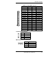
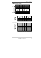
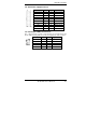
J10: Floppy Drive Connector
J10 is a slim 26-pin connector and will support up to 2.88MB FDD.
Signal Name Pin # Pin # Signal Name
VCC 1 2 INDEX
VCC 3 4 DRV_SEL
VCC 5 6 DSK_CH
NC 7 8 NC
NC 9 10 MOTOR
DINST 11 12 DIR
NC 13 14 STEP
GND 15 16 WDATA
GND 17 18 WGATE
GND 19 20 TRACK
NC 21 22 WPROT
GND 23 24 RDATA
GND 25 26 SIDE
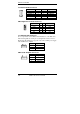
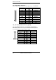
J11, J12: Serial ATA Connectors (option)
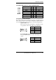
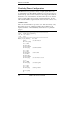
J13, J9: LVDS Connectors (1st channel, 2nd channel)
The LVDS connectors are composed of the first channel (J13) and
second channel (J9) to support 24-bit or 48-bit.
Signal Name Pin # Pin #
Signal Name
TX0- 2 1 TX0+
Ground 4 3 Ground
TX1- 6 5 TX1+
5V/3.3V 8 7 Ground
TX3- 10 9 TX3+
TX2- 12 11 TX2+
Ground 14 13 Ground
TXC- 16 15 TXC+
5V/3.3V 18 17 ENABKL
+12V 20 19 +12V