
Computer Hardware User Manual

INSTALLATIONS
AR-B1760 User’s Manual 19
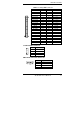
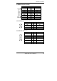
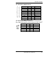
J4: Gigabit LAN Connector (used with ID240/option)
Signal Name Pin Pin Signal Name
MDI0+ 1 9 MDI0-
2.5V 2 10 GND
MDI1+ 3 11 MDI1-
MDI2+ 4 12 MDI2-
2.5V 5 13 2.5V
MDI3+ 6 14 MDI3-
ACT_LED 7 15 LINK_UP
Link1000_LED 8 16 Link100_LED
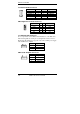
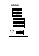
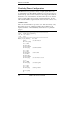
J5: System Function Connector
J5 provides connectors for system indicators that provide light indication
of the computer activities and switches to change the computer status. J5
is a 16-pin header that provides interfaces for the following functions.
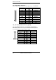
Speaker: Pins 1 - 4
This connector provides an interface to a speaker for audio
tone generation. An 8-ohm speaker is recommended.
Pin # Signal Name
1 Speaker out
2 No connect
3 Ground
4 +5V
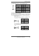
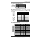
Power LED: Pins 9-11
The power LED indicates the status of the main power
switch.
Pin # Signal Name
9 Power LED
10 NC
11 Ground