AP440FX Motherboard Technical Product Specification May, 1997 Order Number 281830-002 The AP440FX motherboard may contain design defects or errors known as errata which may cause the product to deviate from published specifications. Current characterized errata are documented in the AP440FX Motherboard Specification Update.
Revision History Revision Revision History Date -001 Release of the AP440FX Technical Product Specification. 7/96 -002 Second release of the AP440FX Technical Product Specification 5/97 This product specification applies only to standard AP440FX motherboards with BIOS identifier 1.00.0x.CT1. Changes to this specification will be published in the AP440FX Motherboard Specification Update (Order Number: 281831) before being incorporated into a revision of this document.
Table of Contents 1 Motherboard Description 1.1 1.2 1.3 1.4 1.5 1.6 1.7 1.8 1.9 1.10 1.11 1.12 1.13 1.14 Overview...................................................................................................................... 7 Motherboard Manufacturing Options ........................................................................... 9 Form Factor ................................................................................................................. 9 I/O Shield....................
AP440FX Motherboard Technical Product Specification 1.15 Environmental............................................................................................................ 38 1.16 Power Consumption .................................................................................................. 38 1.16.1 Power Supply Considerations ..................................................................... 39 1.17 Regulatory Compliance......................................................................
Contents 4 Error Messages and Beep Codes 4.1 4.2 4.3 4.4 BIOS Beep Codes ..................................................................................................... 71 PCI Configuration Error Messages ............................................................................ 71 BIOS Error Messages ................................................................................................ 73 ISA NMI Messages ..................................................................................
AP440FX Motherboard Technical Product Specification 32. 33. 34. 35. 36. 37. 38. 39. 40. 41. 42. 43. 44. 45. vi Interrupts ................................................................................................................... 44 Flash Memory Organization....................................................................................... 45 Recommendations for Configuring an ATAPI Device ................................................ 46 Overview of the Setup Menu Screens .................
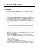
1 Motherboard Description 1.1 Overview The AP440FX motherboard is a 64-bit, high-performance, mixed-voltage, energy-conscious, highly integrated platform. The AP440FX motherboard supports the following set of features: • • • • • • • • • • • Uses a 9-inch by 13-inch LPX form factor. Uses a type 8 Zero Insertion Force (ZIF) socket to house the standard processor, and provides an upgrade path to future OverDrive® processors.
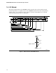
AP440FX Motherboard Technical Product Specification A B C D E F G H I J K L MM LL KK JJ II HH GG FF M N O P Q EE R DD CC S T U V BB AA Z Y X W OM06178 Figure 1. Motherboard Features Table 1.
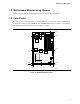
Motherboard Description 1.2 Motherboard Manufacturing Options Contact your local Intel Field Sales Office for options and ordering information. 1.3 Form Factor The motherboard is designed to fit into a standard LPX form factor chassis. Figure 2 illustrates the mechanical form factor for the AP440FX. The AP440FX LPX form factor adheres to the standard LPX guidelines with outer dimensions of 9 inches x 13 inches. 7.10 12.63 10.98 5.50 0.37 0.00 0.150 8.65 0.35 3.55 0.00 7.15 8.45 OM06179 Figure 2.
AP440FX Motherboard Technical Product Specification 1.4 I/O Shield The back panel I/O shield for the AP440FX motherboard must meet specific dimensional and material requirements. Computers based on the AP440FX motherboard need the back panel I/O shield in order to pass certification testing. Figure 3 shows the critical dimensions for the I/O shield and indicates the position of each cutout. 0.118 0.235 0.900 0.682 0.525 2.534 3.945 4.645 5.302 5.963 6.904 8.193 9.000 0.021 0.080 0.
Motherboard Description 1.5 Microprocessor The AP440FX motherboard operates with 2.1 V to 3.5 V Pentium Pro processors. An onboard voltage regulator circuit provides the required voltages from the 5 V and 3.3 V taps off the power supply. The onboard voltage regulator makes use of the VID capabilities to automatically adjust its voltage output to match that of the installed processor. Pentium Pro processors running at 150, 166, 180, and 200 MHz are supported.
AP440FX Motherboard Technical Product Specification 1.6 Main System Memory The motherboard has four 72-pin tin-lead SIMM sockets that make it possible to install up to 128 MB of RAM. The sockets support 1M x 32 (4 MB) single-sided modules, 2M x 32 (8 MB), 4M x 32 (16 MB), and 8M x 32 (32 MB) single- or double-sided modules. Minimum memory size is 8 MB and maximum memory size, using four 8M x 32 SIMM modules, is 128 MB.
Motherboard Description • • • 1.7.2 Integrated DRAM controller 64/72-bit Non-Interleaved path to memory w/ ECC support Support for EDO and Fast Page DRAM 8 MB to 256 MB main memory Fully synchronous PCI bus interface PCI Rev. 2.
AP440FX Motherboard Technical Product Specification 1.7.4 IDE Support The motherboard provides two independent high performance bus-mastering PCI IDE interfaces capable of supporting PIO Mode 3 and Mode 4 devices. The BIOS supports Logical Block Addressing (LBA) and Extended Cylinder Sector Head (ECHS) translation modes as well as ATAPI (e.g., CD-ROM) devices on both IDE interfaces. Detection of IDE device transfer rate and translation mode capability is automatically determined by the BIOS.
Motherboard Description 1.8 PC87307 Super I/O Controller Control for the integrated serial ports, parallel port, floppy drive, real-time clock, and keyboard controller is incorporated into a single component, the National Semiconductor PC87307.
AP440FX Motherboard Technical Product Specification • • 1.8.3 : Power down and coffee-break key sequences take advantage of the SMM features of the Pentium Pro processor to greatly reduce the computer’s power consumption while maintaining the responsiveness necessary to service external interrupts. : Keyboard secure hot keys lock the keyboard until user specified password is given.
Motherboard Description 1.9.1 S3 ViRGE Graphics Subsystem The AP440FX motherboard is available with a factory option of an S3 ViRGE SVGA graphics controller with 2 MB of 50 ns EDO SOJ DRAM. The S3 ViRGE has a high performance 64-bit 2D/3D graphics engine and incorporates the S3 Streams Processor that enables the device to convert YUV formatted video data to RGB and provides acceleration for scaling the video display without compromising picture quality or frame rate.
AP440FX Motherboard Technical Product Specification 1.9.
Motherboard Description 1.10 Audio Subsystem The AP440FX motherboard features a 16-bit stereo audio subsystem as a factory installed option. The audio subsystem is based on the Crystal CS4236 multimedia codec. The CS4236 provides all the digital audio and analog mixing functions required for playing and recording of audio on personal computers.
AP440FX Motherboard Technical Product Specification When an out-of-range condition (temperature, fan speed, or voltage) is reached, an interrupt is activated. The Management Extension circuitry connects to the ISA bus as an 8-bit I/O mapped device and uses the I/O addresses identified in the I/O map. 1.
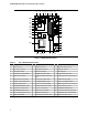
Motherboard Description Serial J3N1 9 J9L1 Bank 0(J6J1, J7J1) Bank 1(J7J2, J7J3) 8 2 Audio PCI/ISA Riser Connector(J6J2) 1 7 2 1 Wavetable 4 COM2H 8 CD-ROM 1 J9N1 1 J9K1 Video 1 Telephony 2 LPB VESA J1K1 Power 28 33 1 34 3.3V Power 1 J9J1 6 Primary Power Floppy/IDE 1 5 Secondary Primary 2 Floppy Drive 3 J8L1 1 1 33 J9H1 J9F1 2 PCI IDE J3A1 J4A1 3 1 J8H1 J9H2 Aux.
AP440FX Motherboard Technical Product Specification 1.12.1 Front Panel Connectors The AP440FX motherboard provides connectors to support functions typically located on the chassis bezel. In addition, connectors are provided that support a cooling fan and a keyboard lock.
Motherboard Description 1.12.1.1 SW_ON This 2-pin header connects to a front panel power switch. When the switch is closed, the power supply turns on. If a mechanical switch is connected to this header, it must apply a momentary ground to the SW_ON header pin in order to signal the supply to turn on or off. Because of the motherboard’s internal debounce circuitry, the ground must be applied for at least 50ms.
AP440FX Motherboard Technical Product Specification 1.12.1.6 Reset This 2-pin header can be connected to a momentary SPST type switch that is normally open. When the switch is closed, the computer performs a hard reset and runs POST. 1.12.1.7 Speaker The speaker provides error beep code information during the POST, if the computer cannot use the video interface. Jumpering pins 26-27 (the last two pins of J2A1) engage the onboard speaker.
Motherboard Description 1.12.2 Memory/Expansion Connectors The AP440FX motherboard has four 72-pin SIMM sockets for main memory. These sockets accept standard SIMM 72-pin modules, as long as they satisfy the requirements described in the “Main System Memory” section of this specification, starting on page 12. The AP440FX motherboard uses a PCI/ISA riser connector (J6J2) to provide for expansion PCI or ISA boards. The associated riser board can support either two or three PCI slots.
AP440FX Motherboard Technical Product Specification Table 7. PCI/ISA Riser Connector (J6J2) (continued) Pin Signal Name Pin Signal Name Pin Signal Pin Signal Name A19 SA12 B19 REFRESH# E19 AD26 F19 AD25 A20 SA11 B20 SYSCLK E20 AD24 F20 CBE3# A21 SA10 B21 IRQ7 E21 AD22 F21 AD23 A22 SA9 B22 IRQ6 E22 AD20 F22 AD21 A23 SA8 B23 IRQ5 E23 AD18 F23 AD19 A24 SA7 B24 IRQ4 E24 3.3 V F24 3.
Motherboard Description 1.12.3 VESA Feature Connector Table 8 provides the pinout and signal listing for the LBP VESA feature connector. Table 8.
AP440FX Motherboard Technical Product Specification 1.12.5 Audio Connectors The pinouts and signal listings for the audio connectors are provided in Table 10, Table 11, and Table 12. Table 10. Pin Signal Name 1 Ground 2 CD-Left 3 Ground 4 CD-Right Table 11. Wavetable Upgrade Connector (J9L1) Pin Signal Name 1 Wave Right 2 Ground 3 Wave Left 4 Ground 5 Key 6 Midi_In 7 NC 8 MIDI_Out Table 12.
Motherboard Description 1.12.6 Power Supply Connectors The AP440FX motherboard must be used with a power supply that supports remote power on/off, so the motherboard can turn off the power under software control. The Powerman utility supplied for Windows 3.1x allows for soft-off as does the shutdown icon in Windows 95 Start menu. The BIOS turns the power off when it receives the proper APM command from the operating system.
AP440FX Motherboard Technical Product Specification The pinout listing for the soft-off power supply connector of the AP440FX motherboard is shown in Table 15. This 3-pin, keyed position supports a software-controlled power supply shutoff (softoff). When connected to this position, the power supply follows remote on/off commands. Table 15. Soft-Off Power Supply Connector (J9F1) Pin Name Function 1 +5 VSB +5 Volts Standby 2 PS_ON Remote On/Off 3 PS_COM Supply presence 1.12.
Motherboard Description Table 17 lists the pinout and signal names for the IDE connectors. Table 17.
AP440FX Motherboard Technical Product Specification 1.12.8 Back Panel Connectors Figure 7 shows the location of the back panel connectors. PS/2 Mouse Audio Out Mic Input Parallel Port PS/2 Keyboard USB 1 USB 2 Serial Port 1 VGA Video OM06183 Figure 7. I/O Connections 1.12.8.1 VGA Video Connector Table 18 lists the pinout and signal names for the VGA video connector. Table 18.
Motherboard Description 1.12.8.2 COM1 Serial Port Table 19 lists the pinout and signal names for the serial connectors. Table 19. Serial Port Connector Pinout Pin Signal Name Description 1 DCD Carrier Detect 2 SIN# Serial Data In 3 SOUT# Serial Data Out 4 DTR# Data Terminal Ready 5 GND Chassis Ground 6 DSR# Data Set Ready 7 RTS# Request To Send 8 CTS# Clear To Send 9 RI Ring Indicator 1.12.8.
AP440FX Motherboard Technical Product Specification 1.12.8.5 Parallel Port Table 22 lists the pinout and signal names for the parallel port connector. Table 22.
Motherboard Description 1.13 Jumper Settings There are three jumper blocks on the AP440FX motherboard. The jumper block at J1J1 defines the number of PCI slots (two or three slots) available on the riser board used with the motherboard. The jumper block at J4L2 defines a range of microprocessor and motherboard configuration parameters. The jumper block at J8A2 is used to provide 3.5 V for processors that require that voltage.
AP440FX Motherboard Technical Product Specification 1.13.1 Microprocessor Configuration (J4L2) These allow the motherboard to be switched between different speeds of the Pentium Pro processor. These jumpers also affect the PCI and ISA clock speeds as shown in Table 23. Table 23. Microprocessor/System Speed Settings J4L2-A J4L2-B J4L2-C Host Bus Microprocessor Microprocessor Freq. Clock Multiplier Freq. (MHz) (MHz) PCI Bus Freq. (MHz) ISA Bus Freq. (MHz) DOWN DOWN DOWN 2.5 150 60 30 7.
Motherboard Description Table 24 lists the motherboard configuration jumper positions and indicates the meaning for each position. Table 24. Configuration Jumper Settings Function Jumper Configuration FDWPR - Flash Write Protect J4L2-D, 5-6 J4L2-D, 4-5 UP - NOR (Default), Normal operation DOWN - PRT, Protect FLASH - Flash Recover J4L2-E, 2-3 J4L2-E, 1-2 UP - NOR (Default), Normal operation DOWN - REC - Enable Top Boot block to recover Flash.
AP440FX Motherboard Technical Product Specification 1.15 Environmental Table 25. Motherboard Environmental Specifications Parameter Specification Temperature o o Non-Operating -40 C to +70 C Operating +0 C to +55 C o o DC Voltage +3.3 V ±5 % +5 V ±5 % -5 V ±5 % +12 V ±5 % -12 V ±5 % Vibration Unpackaged 5 Hz to 20 Hz : 0.01g² Hz sloping up to 0.02 g² Hz 20 Hz to 500 Hz : 0.02g² Hz (flat) Packaged 10 Hz to 40 Hz : 0.015g² Hz (flat) 40 Hz to 500 Hz : 0.015g² Hz sloping down to 0.
Motherboard Description 1.16.1 Power Supply Considerations The AP440FX motherboard is designed to operate with a switching power supply in the PS/2 form-factor with dual line input capability, remote ON/OFF, forced air cooling, standby voltage (VSB), and the following electrical characteristics: • • • • Power - 200 W maximum peak, 160 W maximum continuous Rise time for power supply - 2 ms to 20 ms Minimum delay from reset to Powergood - 100ms Minimum Powerdown warning - 1 ms Table 27.
AP440FX Motherboard Technical Product Specification 1.17.1.5 EMKO-TSE (74-SEC) 207/94 Summary of Nordic deviations to EN 60 950. (Norway, Sweden, Denmark & Finland) 1.17.2 1.17.2.1 EMI FCC Class B Title 47 of the Code of Federal Regulations, Parts 2 & 15, Subpart B, pertaining to unintentional radiators. (USA) 1.17.2.2 CISPR 22, 2nd Edition, 1993 Limits and methods of measurement of Radio Interference Characteristics of Information Technology Equipment. (International) 1.17.2.
2 Motherboard Resources 2.1 Memory Map Table 28.
AP440FX Motherboard Technical Product Specification 2.2 I/O Map Table 29.
Motherboard Resources 2.3 Soft-Off Control The motherboard design uses Soft-off control implemented under the SMM code in the BIOS. Any power supply used with the AP440FX motherboard must support the Soft-off feature. The ONCTL# pin of the I/O controller is connected to the Soft-off control line in the power supply circuit. The registers in the I/O controller that set the I/O address and control the ONCTL# pin are not setup until the SMM code is activated. 2.4 PCI Configuration Space Map Table 30.
AP440FX Motherboard Technical Product Specification 2.6 Interrupts Table 32.
3 Motherboard BIOS and Setup Utility 3.1 Introduction The AP440FX motherboard uses an Intel BIOS, which is stored in flash memory and easily upgraded using a floppy disk-based program. In addition to the Intel BIOS, the flash memory also contains the Setup utility, Power-On Self Tests (POST), APM 1.2, the PCI auto-configuration utility, and Windows 95 ready Plug and Play 1.0a. This motherboard also supports BIOS shadowing, allowing the BIOS to execute from 64-bit onboard write-protected DRAM.
AP440FX Motherboard Technical Product Specification The disk-based Flash upgrade utility, FMUP.EXE, has three options for BIOS upgrades: • • • The Flash BIOS can be updated from a file on a disk. The current BIOS code can be copied from the Flash EEPROM to a disk file as a backup in the event that an upgrade cannot be successfully completed. The BIOS in the Flash device can be compared with a file to ensure the computer has the correct version.
Motherboard BIOS and Setup Utility PCI specification 2.1 for add-in card auto-configuration is also a part of the Plug and Play BIOS. Peer-to-peer hierarchical PCI Bridge 1.0 is supported, and by using an OEM supplied option ROM or TSR, a PCI-to-PCMCIA bridge capability is possible as well. 3.6 ISA Plug and Play The BIOS incorporates ISA Plug and Play capabilities as delivered by Plug and Play Release 1.0A (Plug and Play BIOS V.. 1.0A, ESCD V.. 1.03).
AP440FX Motherboard Technical Product Specification 3.8 Advanced Power Management (APM) This section describes the use of System Management Mode (SMM) by the BIOS. The BIOS supports APM version 1.2. APM is enabled in BIOS by default; however, the computer must be configured with an APM driver to utilize the system power saving features. Windows 95 enables APM automatically upon detecting the presence of the APM BIOS.
Motherboard BIOS and Setup Utility 3.10 Language Support The BIOS setup screen and help messages are supported in 32 languages. There are 5 languages available at this time: American English, German, Italian, French, and Spanish. Translation to other languages may become available at a later date. 3.11 Boot Options Booting from CD-ROM is supported in adherence to the “El Torito” v. 1.0 bootable CD-ROM format specification developed by Phoenix Technologies and IBM.
AP440FX Motherboard Technical Product Specification Table 35. Overview of the Setup Menu Screens Setup Menu Screen Description Main Set up and modify some of the basic options of a PC, such as time, date, diskette drives, hard drives. Advanced Modify the more advanced features of a PC, such as peripheral configuration and advanced chipset configuration. Security Specify passwords that can be used to limit access to the computer. Exit Save or discard changes.
Motherboard BIOS and Setup Utility 3.14.1.5 Primary IDE Slave Reports if an IDE device is connected to the computer. When selected, this brings up the IDE Device Configuration subscreen. 3.14.1.6 Secondary IDE Master Reports if an IDE device is connected to the computer. When selected, this brings up the IDE Device Configuration subscreen. 3.14.1.7 Secondary IDE Slave Reports if an IDE device is connected to the computer. When selected, this brings up the IDE Device Configuration subscreen. 3.14.
AP440FX Motherboard Technical Product Specification 3.14.2.3 Floppy A: Type Specifies the physical size and capacity of the floppy drive. The options are: • • • • • • 3.14.2.4 Disabled 360 KB, 5.25-inch 1.2 MB, 5.25-inch 720 KB, 3.5-inch 1.44/1.25 MB, 3.5-inch (default) 2.88 MB, 3.5-inch. Floppy B: Type Specifies the physical size and capacity of the floppy drive. The options are: • • • • • • 3.14.3 Disabled (default) 360 KB, 5.25-inch 1.2 MB, 5.25-inch 720 KB, 3.5-inch 1.44/1.25 MB, 3.5-inch 2.
Motherboard BIOS and Setup Utility 3.14.3.3 Heads If IDE Device Configuration is set to User Definable, you must type the correct number of heads for your IDE device. If IDE Device Configuration is set to Auto Configured, this reports the number of heads for your IDE device and cannot be modified. 3.14.3.4 Sectors If IDE Device Configuration is set to User Definable, you must type the correct number of sectors for your IDE device.
AP440FX Motherboard Technical Product Specification 3.14.4 Boot Options Subscreen This section describes the options available on the Boot Options subscreen. 3.14.4.1 First Boot Device Sets which drive the computer checks first to find a bootable operating system. The options are: • • • • • 3.14.4.2 Disabled Floppy (default) Hard Disk CD-ROM Network Second Boot Device Sets which drive the computer checks second to find a bootable operating system. The options are: • • • • 3.14.4.
Motherboard BIOS and Setup Utility 3.14.4.7 Num Lock Sets the state of the Num Lock feature on your keyboard when you boot. The options are: • • Off (default) On 3.14.4.8 Setup Prompt Turns on (or off) the “Press Key if you want to run Setup” prompt during the power-up sequence. The options are: • • ✏ Disabled Enabled (default) NOTE This option has no effect on your ability to access the Setup program. It only toggles the prompt. 3.14.4.
AP440FX Motherboard Technical Product Specification 3.14.4.11 Typematic Rate Delay Sets how long it takes (in milliseconds) for the key-repeat function to start when you hold down a key on the keyboard. The options are: • • • • 250 msec (default) 500 msec 750 msec 1000 msec If Typematic Rate Programming is set to Default, this option is not visible. 3.14.4.12 Typematic Rate Sets the speed (in characters per second) at which characters repeat when you hold down a key on the keyboard.
Motherboard BIOS and Setup Utility 3.14.5.2 Processor Speed Reports the microprocessor clock speed. There are no options. 3.14.5.3 Cache Size Reports the size of the secondary cache. There are no options. If your computer contains no L2 cache, this item does not appear. 3.14.5.4 Peripheral Configuration When selected, this brings up the Peripheral Configuration subscreen. 3.14.5.5 Advanced Chipset Configuration When selected, this brings up the Advanced Chipset Configuration subscreen. 3.14.5.
AP440FX Motherboard Technical Product Specification 3.14.7.4 Serial Port 1 Interface Configures serial port 1. The options are described and listed in Table 36. The default option is Auto Configured. If the Configuration Mode is set to Auto Configured, the Setup program assigns the first free COM port (normally COM1, 3F8h) to serial port 1. Table 36.
Motherboard BIOS and Setup Utility 3.14.7.7 Parallel Port Interface Selects the address and IRQ of the parallel port. The options are described and listed in Table 37. If the Configuration Mode is set to Auto Configured, the Setup program assigns LPT1, 378h, IRQ7 to the parallel port. Table 37.
AP440FX Motherboard Technical Product Specification Table 38 lists and describes the options that are available if the parallel port mode is ECP. Table 38. ECP - Compatible Configuration Options Option Description Disable Port not enabled LPT1, 378, IRQ7, DMA3 Enabled as LPT1 at indicated I/O address, IRQ, and DMA channel. LPT2, 278, IRQ7, DMA3 Enabled as LPT2 at indicated I/O address, IRQ, and DMA channel. LPT1, 378, IRQ5, DMA3 Enabled as LPT1 at indicated I/O address, IRQ, and DMA channel.
Motherboard BIOS and Setup Utility 3.14.7.13 Secondary PCI IDE Status Displays the current status of the Secondary PCI IDE Interface from the selectable setting above. This is an informational field and is not accessible. 3.14.7.14 Floppy Status Reports the current status of the floppy drive from the selectable setting above. There are no options. 3.14.7.15 Serial Port 1 Status Reports the current status of serial port 1 from the selectable setting above. There are no options. 3.14.7.
AP440FX Motherboard Technical Product Specification 3.14.8.4 Onboard Video IRQ Enables or disables the onboard video IRQ. The options are: • • 3.14.8.5 Disabled (default) Enabled Video Palette Snoop Controls the ability of a primary PCI graphics controller to share a common palette with an ISA add-in video card. Some add-in cards that use the VESA feature connector might need this feature enabled. The options are: • • 3.14.8.
Motherboard BIOS and Setup Utility 3.14.8.8 Memory Error Detection Sets the type of error detection or correction. The options are: • • • Disabled (default) ECC Parity This field appears if either ECC or Parity SIMMs are detected. Parity and ECC SIMMs can be configured to run either as Parity or ECC (e.g. Parity SIMMs may be configured to run in ECC mode.) 3.14.8.9 Bank 0 Reports the type of memory found in the Bank 0 SIMM slots. There are no options. 3.14.8.
AP440FX Motherboard Technical Product Specification 3.14.9.4 Inactivity Timer (Minutes) Sets how long the computer must be inactive before it enters power managed mode. Enter the number of minutes. The range is 0 to 255 minutes. The default is 10 minutes. This field does not appear if APM is disabled. 3.14.9.5 Hot Key (CTRL - ALT-) Sets the hot key that, when pressed while holding down the and keys, causes the computer to enter power managed mode. All alphanumeric keys are valid.
Motherboard BIOS and Setup Utility 3.14.10.3 ISA Shared Memory Size Sets a range of memory addresses that will be directed to the ISA bus rather than on-board memory. The options are: • • • • • • • Disabled (default) 16 KB 32 KB 48 KB 64 KB 80 KB 96 KB If this is set to Disabled, the ISA Shared Memory Base Address (described below) will not be visible. This field should be set to Enabled only when a non Plug and Play ISA card (legacy card) that requires non-ROM memory space is used.
AP440FX Motherboard Technical Product Specification 3.14.10.5 IRQ 3, 4, 5, 7, 9, 10, 11, 12, 14, 15 Sets the status of the IRQ. The options are: • • Available (default) Used By ISA Card The PCI auto-configuration code looks here to see if these interrupts are available for use by a PCI or Plug and Play device. If an interrupt is available, the PCI auto-configuration code or the PnP configuration agent can assign the interrupt to be used by the PCI or PnP device.
Motherboard BIOS and Setup Utility 3.14.11.5 Clear Event Log Sets a flag that clears the event log on the next pass through the POST. The options are: • • Keep (default) On Next Boot 3.14.11.6 Mark Existing Events as Read Marks all events already in the log as having been not read (Do Not Mark) or read (Mark). The options are: • • Do Not Mark (default) Mark 3.14.11.
AP440FX Motherboard Technical Product Specification 3.14.12 Security Screen This section describes the two access modes that can be set using the options found on the Security screen, and then describes the Security screen options themselves. 3.14.12.1 Administrative and User Access Modes The options on the Security screen menu enable you to restrict access to the Setup program by enabling you to set passwords for two different access modes: Administrative mode and User mode.
Motherboard BIOS and Setup Utility 3.14.13.4 Set Administrative Password Sets the Administrative password. The password can be up to seven alphanumeric characters. 3.14.14 Exit Screen This section describes the different ways to exit and save or not save changes made in the Setup program. 3.14.14.1 Exit Saving Changes Saves the changes to CMOS RAM and exits the Setup program. You can also press the key anywhere in the Setup program to initiate this. 3.14.14.
4 Error Messages and Beep Codes 4.1 BIOS Beep Codes Table 41. BIOS Beep Codes Beeps Error Message Description 1 Refresh Failure The memory refresh circuitry on the motherboard is faulty. 2 Parity Error A parity error has been detected. 3 Base 64 KB Memory Failure Memory failure in the first 64 KB. 4 Timer Not Operational Memory failure in the first 64 KB of memory, or Timer 1 on the motherboard is not functioning.
AP440FX Motherboard Technical Product Specification Table42. PCI Configuration Error Messages (continued) Error Message Explanation NVRAM Cleared By Jumper The “Clear CMOS” jumper has been moved to the “CLR” position and CMOS RAM has been cleared. NVRAM Data Invalid, NVRAM Cleared Invalid entry in the ESCD. Static Device Resource Conflict A non Plug and Play ISA card has requested a resource that is already in use.
Error Messages and Beep Codes 4.3 BIOS Error Messages Table 44. BIOS Error Messages Error Message Explanation Gate A20 Error Gate A20 on the keyboard controller is not working. Address Line Short! Error in the address decoding circuitry on the motherboard. Cache Memory Bad, Do Not Enable Cache! Cache memory is defective. Replace it. CH-2 Timer Error There is an error in timer 2. CMOS Battery State Low CMOS RAM is powered by a battery. The battery power is low. Replace the battery.
AP440FX Motherboard Technical Product Specification 4.4 ISA NMI Messages Table 45. 74 ISA NMI Messages ISA NMI Message Explanation Memory Parity Error at xxxxx Memory failed. If the memory location can be determined, it is displayed as xxxxx. If not, the message is Memory Parity Error ????. I/O Card Parity Error at xxxxx An expansion card failed. If the address can be determined, it is displayed as xxxxx. If not, the message is I/O Card Parity Error ????.