9EJL4 Intel® Socket 478 Intel® 845PE + ICH4 ATX Motherboard User’s Guide Version 1.
Declaration of Conformity According to 47 CFR, Parts 2 and 15 of the FCC Rules The following designated product: EQUIPMENT: MAINBOARD MODEL NO.: 9EJL4 is a Class B digital device that complies with 47 CFR Parts 2 and 15 of the FCC Rules. Operation is subject to the following two conditions: 1. This device may not cause harmful interference. 2. This device must accept any interference received, including interference that may cause undesired operation.
Federal Communications Commission Statement This device complies with FCC Rules Part 15. Operation is subject to the following two conditions: * This device may not cause harmful interference. * This device must accept any interference received, including interference that may cause undesired operation. This equipment has been tested and found to comply with the limits for a Class B digital device, pursuant to Part 15 of the FCC Rules.
TABLE OF CONTENTS Chapter 1 Introduction............................................................... 1 1-1 Product Specifications .....................................................................................1 1-2 Package Contents.............................................................................................2 1-3 9EJL4 Motherboard Layout.............................................................................3 Chapter 2 Hardware Setup ............................................
Chapter 1 Chapter 1 Introduction 1-1 Product Specifications Processor - Supports Intel® Celeron/Pentium 4 Socket 478 CPU with Hyper-Threading Technology - Supports Intel® Celeron / Pentium 4 system bus at 400/533/800MHz (FSB 800 is conditionally supported.
Chapter 1 Fast Ethernet /Home Networking Controller - On-board LAN chip RTL8101L supports 10/100Mbps Fast Ethernet Boot-Block Flash ROM - Award system BIOS supports PnP, APM, DMI, ACPI, & Multi-device booting features. 1-2 Package Contents This product comes with the following components: 1. Motherboard x1 2. 40-Pin UDMA-100 IDE Cable x1 Blue to motherboard, Gray to Master and Black to Slave 3. 34-Pin floppy Disk Drive Cable x1 2 4. User’s Guide x1 5.
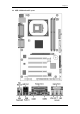
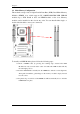
Chapter 1 1-3 9EJL4 Motherboard Layout 3
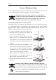
Chapter 2 Chapter 2 Hardware Setup If your motherboard has already been installed in your computer you may still need to refer to this chapter if you plan to upgrade your system's hardware. This motherboard is electrostatic sensitive. Do not touch without wearing proper safety gadget and make sure to disconnect the power cable from the power source before performing any work on your motherboard.
Chapter 2 2-2 Setting your CPU’s Parameters Intel “Hyper-Threading Technology” To enabling the functionality of Hyper-Threading Technology for your computer system you require ALL of the following platform components: CPU: An Intel® Pentium® 4 Processor with HT Technology; Chipset: An Intel® Chipset that supports HT Technology; BIOS: A BIOS that supports HT Technology and has it enabled; OS: An operating system that supports HT Technology.
Chapter 2 2-3 Main Memory Configuration This motherboard provides 2 184pin Double Data Rate (DDR) Dual Inline Memory Modules (DIMM) slots, which supports PC 1600/PC2100/2700 DDR SDRAM modules up to 2GB. Install at least one DIMM module on the slots. Memory modules can be installed on the slots in any order. You can install either single- or double-sided modules to meet your own needs. To install your DDR Modules please follow the following steps: 1.
Chapter 2 2-4 Connector and Jumper Settings Connectors are used to link the system board with other parts of the system, including power supply, keyboard, and the various controllers on the front panel of the system case. The power supply connector is the last connection to be made while installing a motherboard. Before connecting the power supply, please make sure it is not connected to the power source. All cables that provided by CHAINTECH come with a security-proof.
Chapter 2 Blinking LED in Suspend Mode: While in Suspend mode, the LED light on the front panel of your computer will flash. Suspend mode is entered by pressing the Green Override Power Button on your ATX case, or by enabling the Power Management and Suspend Mode options in BIOS's Power Management menu. (See section 3.5) Poly-fuse Over Current Protection: The poly-fuse protects the system from dangerous voltages that the system might be exposed to via keyboards or USB connectors.
Chapter 2 Button Operation diagram. 2. P-LED (Power LED Connector): The power indicator LED shows the system's power status. It is important to pay attention to the correct cable and pin orientation (i.e., not to reverse the order of these two connectors.) 3. G-BTN/G-LED (Green Button Switch/LED Connector): Some ATX cases provide a Green button switch, which is used to put the system in Suspend mode.
Chapter 2 IDE 1/2 (IDE Hard-Disk Connector) The motherboard has a 32-bit Enhanced PCI IDE and Ultra ATA66/100 controller that provides PIO mode 0~4, Bus Master, and Ultra ATA66/100 function. This connector is used for connecting 40 pins of ATAPI devices. IDE 1 only connects two IDE devices. (Primary Master/Slave) IDE 2 only connects two IDE devices.
Chapter 2 1. Disconnect the system power supply from the power source. 2. Set the jumper cap at location [2-3] for <5 seconds>, and then set it back to the default position. 3. Connect the system's power and then start the system. 4. Enter BIOS's CMOS Setup Utility and choose Load Setup Defaults. Type [Y] and then press [Enter] to continue. 5. Set the system configuration in the Standard CMOS Setup menu.
Chapter 2 FAN1/FAN2/FAN3 (CPU/System/ North Bridge Cooling Fan Connectors): The board's hardware management is able to detect the CPU and system fan speed in rpm (revolutions per minute). The wiring and plugging may vary depending on the manufacturer. On standard fans, the red is positive (+12V), the black is ground, and the yellow wire is the rotation signal. Connect the north bridge-cooling fan to FAN3.
Chapter 2 CN5 [WOL (Wake-on-LAN) Connector]: Enable the Wake Up On LAN selection in BIOS's Power Management Menu to use this function. The capability to remotely manage PCs on a network is a significant factor in reducing administrative and ownership costs. Magic Packet technology is designed with WOL capability to LAN controller. This header is used to connect an add-in NIC (Network Interface Card) that provides WOL function to the motherboard.
Chapter 2 CN23/CN23A (CBOX™ 2 Front USB Connector for USB 2/3 and 4/5): USB Port 2/3 CN23, USB Port 4/5 CN23A If you want to use a USB Keyboard, you must enable the USB keyboard support function in BIOS's Integrated Peripherals menu (See Section 3.4). This board contains a USB Host controller and a root hub with two connectors is also included for an optional USB Adaptor (USB 2/3 and 4/5). CN24 (CBOX™ 2 Front Audio Connector): This connector gives you the option of a front panel audio jack cable ext.
Chapter 3 Chapter 3 BIOS Setup Program Phoenix-Award BIOS ROM has a built-in setup program that allows users to modify the basic system configuration. This information is stored in CMOS RAM so that it can retain the setup information, even when the power is turned off. To enter the Phoenix-Award BIOS setup program press [Delete] when you Power on or reboot the computer system. The primary screen as shown in Figure 3-1 is a list of the menus and functions available in the setup program.
Chapter 3 3-1 Standard CMOS Setup The Standard CMOS Setup allows users to configure system components such as hard disk drive, floppy disk drive and video display as well as date, time and boot-up error signaling. This configuration menu should be changed when installing a motherboard for the first time, changing hardware in your system such as the HDD, FDD, video display, or when the CMOS data was lost or corrupted.
Chapter 3 POST (Power On Self Test). This function stops the computer if BIOS detects a hardware error. You can tell BIOS to halt on all errors, no errors, or not to halt on specific errors. 3-2 Advanced BIOS Features By choosing the Advanced BIOS Features option from the CMOS Setup Utility menu (Figure 3-1), the screen below displays the manufacturer's default values for the motherboard.
Chapter 3 Hyper-Threading Technology Available options are [Enabled] and [Disabled]. Select [Enable] to support Hyper-Threading Technology and vice versa. Quick Power On Self Test (POST): Enable this function to reduce the amount of time required to run the POST (Power On Self Test). BIOS will save time by skipping some items during POST. It is recommended that you disable this setting. Discovering a problem during boot up is better than loosing data during your work.
Chapter 3 3. Typematic Delay (Msec) The typematic delay sets how long after you press a key that a character begins repeating. Security Option: The Supervisor and/or User Password functions shown in Figure 3-1 must be set to take advantage of this function. See Section 3.11 for password setting information. When the Security Option is set to System, a password must be entered to boot the system or enter the BIOS setup program.
Chapter 3 3-3 Advanced Chipset Features By choosing the [Advanced Chipset Features] option from the CMOS Setup Utility menu (Figure 3-1), the screen below displays the manufacturer's default values for the motherboard. Figure 3-4 Advance Chipset Features All of the above settings have been determined by the motherboard manufacturer and should not be changed unless you are absolutely sure of what you are doing.
Chapter 3 DRAM RAS# Precharge: This item controls the idle clocks after issuing Precharge command to the DRAM. System BIOS Cacheable: Enabling this function allows caching of the system BIOS ROM at F0000h-FFFFFh, which results in better system performance. However, if any program writes to this memory area, a system error may result. It is advised to leave it in default setting. Caching the system BIOS results in better performance than shadowing the system BIOS.
Chapter 3 3-4 Integrated Peripherals This section provides information on setting peripheral devices. By choosing the Integrated Peripherals option from the CMOS Setup Utility menu (Figure 3-1), the screen below displays the manufacturer's default values for the motherboard. Figure 3-5 Integrated Peripherals Screen OnChip IDE Device: Press [Enter] to enter the sub-menu, which contains the following items for advanced control: 1.
Chapter 3 support. OnChip PCI Device: This section provides information on setting the on-board devices. Press [Enter] to enter the sub-menu, which contains the following items for advanced control: 1. AC97 Audio: This feature allows you to enable/disable the on-board AC97 audio function. Super IO Device: This section provides information on setting the Super I/O devices. Press [Enter] to enter the sub-menu, which contains the following items for advanced control: 1.
Chapter 3 10. Midi Port IRQ: This item specifies an IRQ for the Midi port. USB controller: Enable the on-board Universal Serial Bus (USB V1.1 or V2.0) controller if you want to connect a USB device to your system. Note that if this setting is disabled, you can still temporarily use a USB keyboard during boot up so that you can enter BIOS and enable this setting. If you pass the boot up stage without enabling this function, your PS/2 keyboard will no longer work. USB 2.
Chapter 3 3-5 Power Management Setup This section provides information on the Green PC power management functions. By choosing the Power Management Setup option from the CMOS Setup Utility menu (Figure 3-1), the screen below displays the manufacturer's default values for the motherboard. Figure 3-5 Power Management Setup ACPI Suspend Type: This feature allows user to select a suspend type for the operating system to turn off unused peripherals devices, such as CD-ROM players.
Chapter 3 selected Blank. This function serves as both screen and a power saver. 3. DPMS Supported - Select this option if your video card supports the Display Power Management Signaling (DPMS) standard (i.e., you have a monitor that supports Green features). Use software supplied by your video subsystem to set video power management options. Video off In Suspend: If it is set to [Yes] the monitor enters power saving mode. The Power Management function must be enabled to use this function.
Chapter 3 Wake up Events 1. Power On By PCI/Onbrd LAN: When enabled, a PCI interface that receives a signal will activate the system from soft off and green mode. 2. Power On by Modem: When enabled, a Modem will be able to receive a signal and activate the system from soft off and green mode. You should connect the modem to the COM port and call your PC to power on. 3. Wake up on LAN: When enabled, a LAN that receives a signal will activate the system from soft off and green mode. 4.
Chapter 3 3-6 PNP/PCI Configurations This section provides IRQ and DMA setting information. By choosing the PNP/PCI Configuration option from the CMOS Setup Utility menu (Figure 3-1), the screen below displays the manufacturer's default values for the motherboard. Figure 3-6 PNP/PCI Configurations Reset Configuration Data: Default is [Disabled].
Chapter 3 3-7 Frequency/Voltage Control By choosing the Frequency/Voltage Control option from the CMOS Setup Utility menu (Figure 3-1), the screen below displays the manufacturer's default values for the motherboard. Figure 3-8 Frequency/Voltage Control Memory Frequency For Please leave the default system setting [Auto] for a stable system operation. CPU Clock Ratio: This feature allows user to manually configure your CPU clock ratio according to your processor’s specifications.
Chapter 3 Overclockability: This motherboard is designed to support overclocking ability. However, please make sure your components are able to tolerate such abnormal setting, while CPU clock speed is overclocked. Any attempt to operate beyond product specifications is not recommended. We are not responsible for damages caused by inadequate operation or settings beyond product specifications.
Chapter 3 When there is no supervisor password set, the user password controls access to all BIOS settings. 3-11 Save and Exit Setup If you select this and type [Y] (for Yes) followed by [Enter], the values entered in the setup utilities will be recorded in the CMOS memory of the BIOS chip. 3-12 Exit Without Saving Selecting this option and pressing [Y] followed by [Enter] lets you exit the Setup program without recording any new values or changing old ones.
Chapter 4 Chapter 4 DRIVER Setup Insert the support CD that come with your motherboard into your CD-ROM driver or double-click the CD drive icon in [My computer] to open the setup screen. 4-1 Intel® IDE Bus Mastering Drivers Setup 1. Click [Intel® IDE Bus Mastering Drivers] 2. Click [Next] to start software installation. 3. Click [Yes] to accept the license agreement 4. Please, select [Next] 5. Please, select [Finish] after restart 4-2 Ultra ATA storage driver Setup 1. Click [Ultra ATA storage driver] 2.
Chapter 4 4-3 Audio Driver Setup 1. Click [Audio Driver] 2. Click [Next >] to continue installation 3. Click [Finish] to complete setup. 4-4 LAN Driver Setup 1. Click [LAN Driver] 2. Click [Next >] to continue installation 3. Click [Finish] to complete setup. 4-5 USB 2.0 Driver 1. Click [USB 2.0 Driver] 2. Click [Next >] to start software installation. 3. Please click [Next >] to continue. 4. Please click [Yes] to accept the license agreement. 5. Please click [OK] to continue. 6.
How To Contact CHAINTECH NOTE All rights are reserved for the products and corporate names/logos that appear in this manual to their original owners. CHAINTECH reserves all the rights to change this manual .All information is subject to change without notice.
NOTE How To Contact CHAINTECH Please do not hesitate to contact us if you have any problem about our products. Any opinion will be appreciated. For Asia, Africa, Australia and Pacific Island: CHAINTECH COMPUTER CO., LTD No. 7-1, Chung Shin Rd., Tu Cheng, Taipei Hsien, Taiwan, ROC. Tel: +886-2-2268-9998 Fax: +886-2-2269-7510 URL: http://www.chaintech.com.tw E-mail: sales@chaintech.com.tw For Italy and Southern Europe: CELT COMPUTER s.r.l.