
Microcontroller User's Manual


8XC196L
X
SUPPLEMENT
4-6
4.2.3 Peripheral Transaction Server Registers
Figures 4-5 and 4-6 illustrate the PTS interrupt select and service registers for the 8XC196Lx mi-
crocontrollers.
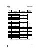
INT_PEND1
Address:
Reset State:
0012H
00H
When hardware detects an interrupt request, it sets the corresponding bit in the interrupt pending
(INT_PEND or INT_PEND1) registers. When the vector is taken, the hardware clears the pending bit.
Software can generate an interrupt by setting the corresponding interrupt pending bit.
7 0
LB
NMI EXTINT — RI TI SSIO1 SSIO0 J1850ST
7 0
LA, LD
NMI EXTINT — RI TI SSIO1 SSIO0 —
Bit
Number
Function
7:0
†
Any set bit indicates that the corresponding interrupt is pending. The interrupt bit is cleared
when processing transfers to the corresponding interrupt vector.
Bit Mnemonic Interrupt Description
NMI Nonmaskable Interrupt
EXTINT EXTINT Pin
Reserved —
RI SIO Receive
TI SIO Transmit
SSIO1 SSIO 1 Transfer
SSIO0 SSIO 0 Transfer
J1850ST J1850 Status (LB only)
†
Bit 5 is reserved on the 8XC196L
x
devices and bit 0 is reserved on the 87C196LA and 83C196LD.
For compatibility with future devices, always write zeros to these bits.
Figure 4-4. Interrupt Pending 1 (INT_PEND1) Register