
Microcontroller User's Manual


8XC196L
X
SUPPLEMENT
11-2
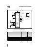
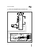
11.3 SLAVE PROGRAMMING CIRCUIT AND ADDRESS MAP
Figure 11-1 shows the circuit diagram and Table 11-3 details the address map for slave program-
ming of the 87C196LA and LB devices.
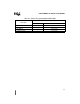
Table 11-2. 87C196LA, LB
OTPROM Address Map
Address Range
(Hex)
Description
7FFF
2080
Program memory
207F
205E
Reserved (each location must contain FFH)
205D
2040
PTS vectors
203F
2030
Upper interrupt vectors
202F
2020
Security key
201F
201C
Reserved (each location must contain FFH)
201B Reserved (must contain 20H)
201A CCB1
2019 Reserved (must contain 20H)
2018 CCB0
2017
2016
OFD flag for QROM or MROM codes
†
2015
2014
Reserved (each location must contain FFH)
2013
2000
Lower interrupt vectors
†
Intel manufacturing uses this location to determine whether to program the OFD bit.
Customers with quick-ROM (QROM) or masked-ROM (MROM) codes who desire oscillator
failure detection should equate this location to the value 0CDEH.