8VM533M-RZ / 8VM533M-RZ-C Intel® Pentium® 4 Processor Motherboard User's Manual Rev. 1003 12ME-VM533MRZ-1003 Copyright © 2004GIGABYTE TECHNOLOGYCO., LTD Copyright by GIGA-BYTETECHNOLOGY CO.,LTD. ("GBT"). No part of this manual may be reproduced or transmitted in any from without the expressed, written permission of GBT. Trademarks Third-party brands and names are the property of their respective owners.
Mother Board 8VM533M-RZ Feb. 20, 2004 Motherboard 8VM533M-RZ Feb.
Preparing Your Computer Computer motherboards and expansion cards contain very delicate Integrated Circuit (IC) chips. To protect them against damage from static electricity, you should follow some precautions whenever you work on your computer. 1. Unplug your computer when working on the inside. 2. Use a grounded wrist strap before handling computer components. If you do not have one, touch both of your hands to a safely grounded object or to a metal object, such as the power supply case. 3.
English Table of Contents Chapter 1 Introduction ................................................................................................ 5 Features Summary ...........................................................................................................................5 8VM533M-RZ Series Motherboard Layout......................................................................................6 Block Diagram ...................................................................................
Features Summary CPU Chipset Memory Slots On-Board IDE On-Board Floppy On-Board Peripherals On-Board LAN * On-Board Sound BIOS I/O Control Hardware M onitor Additional Features Form Factor — — — — — — — — — — — — — — — — — — — — — — — — — — — — — — — — — — — Socket 478 for Intel® Pentium ® 4 (Northwood) with HT Technology Intel® Pentium ® 4 533/400MHz FSB 2nd cache depends on CPU North Bridge: VIA P4M266A/P4M533 South Bridge: VIA VT8235/VT8237R 2 184-pin DDR DIMM sockets, supports up to 2GB DRAM (Ma
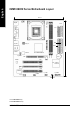
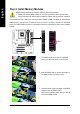
20.8 cm # KB_MS ATX LPT COMA CPU_FAN FDD 8VM533M-RZ LAN * V T6103 * F_AU DIO IDE2 VIA P4M 266A /P4M 533 DDR1 AUDIO IDE1 24.5 cm A TX_12V AGP DDR2 VGA SOC KET 478 R_USB USB English 8VM533M-RZ Series Motherboard Layout BAT PCI1 CODEC V I A V T82 35/ V T8237R PCI2 BIOS PCI3 I TE 8705 F_PANEL F_U SB1 CD_I N COMB PWR_LE D "*" For 8VM533M-RZ only. "#" For8VM533M-RZ-C only.
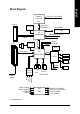
Pentium 4 Socket 478 CPU AGP 4X CPUCLK+/- (100/133MHz) System Bus 533/400MHz VGA Port English Block Diagram 200/266MHz DDR VIA P4M266A/P4M533 MCHCLK (100/133MHz) AGPCLK66 MHz VT6103* MII PCI BUS 33MHz 66MHz V_Link 3 PCI RJ45 * AGPCLK 66MHz 33 MHz 14.318 MHz 48 MHz BIOS VIA LPC BUS VT8235/VT8237R Floppy AC97 Link IT8705 LPT Port PS/2 KB/Mouse 24 MHz MIC LINE-IN PCICLK (33MHz) PCICLK (33MHz) USBCLK (48MHz) 14.
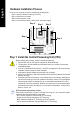
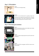
English Hardware Installation Process To set up your computer, you must complete the following steps: Step 1- Install the Central Processing Unit (CPU) Step 2- Install mem ory modules Step 3- Install expansion cards Step 4- Connect ribbon cables, cabinet wires, and power supply Step 4 Step 1 Step 4 Step 2 Step 4 Step 3 Step 1: Install the Central Processing Unit (CPU) Before installing the processor, adhere to the following warning: 1. Please m ake sure the CPU type is supported by the m otherboard.
Socket Actuation Lever English Step 1-1: CPU Installation Figure 1. Pull the rod to the 90-degree directly. Figure 2. Locate Pin 1 in the socket and look for a (golden) cut edge on the CPU upper corner. Insert the CPU into the socket. (Do not force the CPU into the socket.) Then m ove the socket lever to the locked position while holding pressure on the center of the CPU. Step 1-2: CPU Cooling Fan Installation Figure 1.
English Step 2: Install Memory Modules Before installing the m emory modules, adhere to the following warning: 1. Please note that the DIMM module can only fit in one direction due to the one notch. Wrong orientation will cause im proper installation. Please change the insert orientation. The motherboard has 2 dual inline memory m odule (DIM M) sockets. The BIOS will automatically detects memory type and size. To install the memory module, just push it vertically into the DIMM socket.
1. Read the relateAGP card's instruction document before install the AGP card into the computer. 2. If your AGP card has "AGP 4X(1.5V) notch" (show below), please make sure your AGP card is AGP 4X(1.5V). 3. Please carefully pull out the small white- drawable bar at the end of the AGP slot when you try to install/ Uninstall the AGP card. Please align the AGP card to the onboard AGP slot and press firm ly down on the slot .M ake sure your AGP card is locked by the sm all white- drawable bar.
English z LAN port * | Line In jack } Line Out jack LAN is fast Ethernet with 10/100M bps speed. Devices like CD-ROM , walkm an etc. can be connect to Line In jack. Connect the stereo speakers or earphone to this connector. MIC In jack ~ Microphone can be connect to MIC In jack. After installation of the audio driver, you are able to use 2/4/6-channel audio feature by software selection.
English 1) ATX_12V (+12V Power Connector) This connector (ATX_12V) supplies the CPU operation voltage (Vcore). If this "ATX_12V connector" is not connected, system cannot boot. 4 2 Pin No. 1 2 3 4 3 1 Definition GND GND +12V +12V 2) ATX (ATX Power) AC power cord should only be connected to your power supply unit after ATX power cable and other related devices are firmly connected to the mainboard. 11 1 20 10 Pin No. 1 2 3 4 5 6 7 8 9 10 Definition Pin No. 3.3V 11 3.
English 4) FDD (Floppy Connector) Please connect the floppy drive ribbon cables to FDD. It supports 360K, 1.2M, 720K, 1.44M and 2.88M bytes floppy disk types. The red stripe of the ribbon cable must be the sam e side with the Pin1. 34 33 2 1 5) IDE1 / IDE2 (IDE1 / IDE2 Connector) Im portant Notice: Please connect first hard disk to IDE1 and connect CD-ROM to IDE2. The red stripe of the ribbon cable must be the sam e side with the Pin1.
Please connect the power LED, PC speaker, reset switch and power switch etc of your chassisfront panel to the F_PANEL connector according to the pin assignment below.
English 9) F_AUDIO (Front Audio Connector) In order to utilize the front audio header, your chassis must have front audio connector. Also please make sure the pin assigm ent on the cable is the same as the pin assigm ent on the MB header. To find out if the chassis you are buying support front audio connector, please contact your dealer. Please note, you can have the alternative of using front audio connector or of using rear audio connector to play sound. 10 9 2 1 Pin No.
Be careful with the polarity of the COMB connector. Check the pin assignm ent while you connect the COMB cable. Please contact your nearest dealer for optional COMB cable. 2 10 1 9 - 17 - Pin No.
English 8VM533M-RZ Series Motherboard - 18 -
BIOS Setup is an ov erv iew of the BIOS Setup Program. The program that allow s users to modify the basic sy stem configuration. This ty pe of information is stored in battery -backed CM OS RAM so that it retains the Setup information w hen the pow er is turned off. ENTERING SETUP Pow ering ON the computer and pressing immediately w ill allow y ou to enter Setup. If y ou require m ore adv anced BIOS s ettings , pleas e go to "Adv anc ed BIOS" s etting m enu.
English If you can't find the setting you want, please press "Ctrl+F1" to search the advanced option hidden. • Standard CMOS Features This setup page includes all the items in s tandard c ompatible BIOS. • Advanced BIOS Features This setup page includes all the items of Aw ard special enhanced features. • Integrated Peripherals This setup page includes all onboard peripherals. • Power Management Setup This setup page includes all the items of Green func tion features.
CMOS Setup Ut ility-Co pyright (C) 1984 -2003 Aw ard Soft ware Stan dard CM OS Feat ures } } } } Date (mm:dd :yy) Time (hh:mm :ss) Fri, Jan 9 2004 22:3 1:24 IDE IDE IDE IDE [No ne] [No ne] [No ne] [No ne] P rimary M aster P rimary S lave S econdary M aster S econdary Slave Driv e A Driv e B Floppy 3 Mode Su pport [1.44M, 3.
English Drive A / Dri ve B The category identifies the ty pes of floppy disk driv e A or driv e B that has been installed in the computer. None No floppy driv e installed 360K, 5.25" 5.25 inch PC-ty pe standard driv e; 360K by te capacity . 1.2M, 5.25" 5.25 inch AT-ty pe high-density driv e; 1.2M by te capacity (3.5 inch w hen 3 Mode is Enabled). 720K, 3.5" 3.5 inch double-sided driv e; 720K by te capacity 1.44M, 3.5" 3.5 inch double-sided driv e; 1.44M by te capacity . 2.88M, 3.5" 3.
CMOS Setup Ut ility-Co pyright (C) 1984 -2003 Aw ard Soft ware Adva nced BI OS Feat ures Firs t Boot D evice Seco nd Boot D evice Thir d Boot D evice Pas sword C heck CPU H yper-Threa ding [Flo ppy] [HDD -0] [CDR OM] [Set up] [Enab led] # Item Help Menu L evel} Selec t Boot D evice prio rity [Flo ppy] Boot from fl oppy [LS1 20] Boot from L S120 [HDD -0] Boot from Firs t HDD [HDD -1] Boot from Secon d HDD higf: M ove Enter: Select F5: P revious V alues +/-/ PU/PD: V alue F10: Save F6: Fa il-Safe De faul
English Integrated Peripherals CMOS Setup Ut ility-Co pyright (C) 1984 -2003 Aw ard Soft ware Inte grated Periphe rals OnChi p IDE Cha nnel0 OnChi p IDE Cha nnel1 AC97 Audio VIA o nboard L AN * USB 1 .1 Contr oller USB 2 .
Enabled Disabled English USB Keyboard Support Enable USB key board support. Disable USB key board support. (Default v alue) USB Mouse Support Enabled Disabled Enable USB mouse support. Disable USB m ouse support. (Default v alue) Onboard Serial P ort 1 Auto 3F8/ IRQ4 2F8/ IRQ3 3E8/ IRQ4 2E8/ IRQ3 Disabled BIOS w ill autom atically s etup the port 1 address. Enable onboard Serial port 1 and address is 3F8. (Default v alue) Enable onboard Serial port 1 and address is 2F8.
English Power Management Setup CMOS Setup Ut ility-Co pyright (C) 1984 -2003 Aw ard Soft ware Powe r Manag ement S etup ACPI Suspend Type x USB D evice Wa ke-Up Fr om S3 Soft- Off by PWR -BTTN AC B ack Func tion Keybo ard Powe r On Mous e Powe r On PME E vent Wak e Up Resu me by A larm x Date ( of Month) Alarm x Time ( hh:mm:ss) Alarm higf: M ove Enter: Select F5: P revious V alues [S1(P OS)] Disa bled [Instan t-Off] [Soft -Off] [Disa bled] [Disa bled] [Enab led] [Disa bled] Ever yday 0 : 0 : 0 +/-/ PU/
When set at Enabled, any PCI-PM ev ent aw akes the sy stem from a PCI-PM controlled state. This feature requires an ATX pow er supply that prov ides at least 1A on the +5VSB lead. Disabled Disable this function. Enabled Enable PME as w ake up ev ent. (Default v alue) Resume by Alarm You c an set "Resume by Alarm" item to enabled and key in Data/ time to pow er on sy stem. Disabled Disable this function. (Default Value) Enabled Enable alarm function to POWER ON sy stem.
English PC Health Status CMOS Setup Ut ility-Co pyright (C) 1984 -2003 Aw ard Soft ware PC H ealth St atus Vcore DDR 25V +3.3V +12V Curr ent CPU Tempera ture Curren t CPU FAN Speed CPU F AN Fail Wa rning 1.54V 2.5 44V 3.3 60V 11.
CMOS Setup Ut ility-Co pyright (C) 1984 -2003 Aw ard Soft ware Frequ ency/Vol tage Con trol CPU Clock R atio Auto Detect PCI/DIMM Clk Spre ad Spec trum CPU Host Cl ock Con trol ø CPU C lock higf: M ove Enter: Select F5: P revious V alues [15X] [Enab led] [Enab led] [Disa bled] 100 +/-/ PU/PD: V alue F10: Save F6: Fa il-Safe De fault Item Help Menu L evel} ESC: Exit F1: General Help F7: Optimiz ed Defa ults ø This item w ill be av ailable w hen "CPU Host Clock Control" is set to Enabled.
English Load Fail-Safe Defaults CMOS Setup Ut ility-Co pyright (C) 1984 -2003 Aw ard Soft ware } } } } } } } Stan dard CM OS Feat ures Load Fail-Sa fe Defa ults Adva nced BI OS Feat ures Load Optimiz ed Defa ults Inte grated Periphe rals Set Supervis or Pass word Powe r Manag ement S etup Set U ser Pass word PnP/ PCI Con figurat ions Load Fail-Sa fe Defau lts Save (Y/N & )? Exit N S etup PC H ealth St atus Exit Without S aving Frequ ency/Vol tage Con trol higf: Selec t Item F10: Save & Exit S etup ESC: Q
English Set Supervisor/User Password CMOS Setup Ut ility-Co pyright (C) 1984 -2003 Aw ard Soft ware } } } } } } } Stan dard CM OS Feat ures Adva nced BI OS Feat ures Inte grated Periphe rals Powe r Manag ement S etup PnP/ PCI Con figuratEnte ionsr Passw ord: PC H ealth St atus Frequ ency/Vol tage Con trol Load Fail-Sa fe Defa ults Load Optimiz ed Defa ults Set Supervis or Pass word Set U ser Pass word Save & Exit S etup Exit Without S aving higf: Selec t Item F10: Save & Exit S etup ESC: Quit F8: Q- Fla
English Save & Exit Setup CMOS Setup Ut ility-Co pyright (C) 1984 -2003 Aw ard Soft ware } } } } } } } Stan dard CM OS Feat ures Load Fail-Sa fe Defa ults Adva nced BI OS Feat ures Load Optimiz ed Defa ults Inte grated Periphe rals Set Supervis or Pass word Powe r Manag ement S etup Set U ser Pass word PnP/ PCI Con figurat ions Save to CMOS an d EXITSave (Y/ N)? & Exit Y S etup PC H ealth St atus Exit Without S aving Frequ ency/Vol tage Con trol higf: Selec t Item F10: Save & Exit S etup ESC: Quit F8: Q-
English Revision History Chapter 3 Install Drivers Install Drivers Pictures below are shown in Windows XP (CD ver. 2.3) Insert the driver CD-title that came with your motherboard into your CD-ROM drive, the driver CD-title will auto start and show the installation guide. If not, please double click the CD-ROM device icon in "My computer", and execute the setup.exe. INSTALL CHIPSET DRIVER This page shows the drivers that need to be installed for the system.
English Driver install finished!! you have to reboot system!! Item Description n VIA 4IN1 Driver For INF, AGP, IDE and DMA Driver. n VIA KM266/P4M266 VGA Driver n USB Path for WinXP For VIA KM266/P4M266 VGA driver. This patch driver can help you to resolve the USB device wake up S3 hang up issue in XP. n VIA Lan Driver * For VIA LAN driver. n VIA AC97 Audio Driver n VIA USB 2.0 Controller Audio driver for VIA AC97 codec chipset.
English Contact Us — Taiwan (Headquarters) — Japan GIGA-BYTE TECHNOLOGY CO., LTD. NIPPON GIGA-BYTE CORPORATION Address: No.6, Bau Chiang Road, Hsin-Tien, Taipei Hsien, Taiwan WEB address : http://www.gigabyte.co.jp — Singapore TEL: +886 (2) 8912-4888 GIGA-BYTE SINGAPORE PTE. LTD. FAX: +886 (2) 8912-4003 Tech. Support : Tech. Support : http://tw.giga-byte.com/TechSupport/ServiceCenter.htm http://tw.giga-byte.com/TechSupport/ServiceCenter.htm Non-Tech. Support (Sales/Marketing) : Non-Tech.
English — China — Australia NINGBO G.B.T. TECH. TRADING CO., LTD. Tech. Support : GIGABYTE TECHNOLOGY PTY. LTD. Address: 3/6 Garden Road, Clayton, VIC 3168 Australia http://cn.giga-byte.com/TechSupport/ServiceCenter.htm TEL: +61 3 85616288 Non-Tech. Support (Sales/Marketing) : FAX: +61 3 85616222 http://ggts.gigabyte.com.tw/nontech.asp WEB address : http://www.gigabyte.com.cn Tech. Support : http://www.giga-byte.com.au/TechSupport/ServiceCenter.htm Shanghai Non-Tech.