8S651M-RZ / 8S651M-RZ-C Intel Pentium® 4 Processor Motherboard User's Manual Rev. 1001 12ME-8S651MRZ-1001 Copyright © 2003GIGABYTE TECHNOLOGYCO., LTD Copyright by GIGA-BYTETECHNOLOGY CO.,LTD. ("GBT"). No part of this manual may be reproduced or transmitted in any from without the expressed, written permission of GBT. Trademarks Third-party brands and names are the propertyof their respective owners. Notice Please do not remove any labels on motherboard, this may void the warranty of this motherboard.
Mother Board 8S651M-RZ Feb. 20, 2004 Motherboard 8S651M-RZ Feb.
Preparing Your Computer Computer motherboards and expansion cards contain very delicate Integrated Circuit (IC) chips. To protect them against damage from static electricity, you should follow some precautions whenever you work on your computer. 1. Unplug your computer when working on the inside. 2. Use a grounded wrist strap before handling computer components. If you do not have one, touch both of your hands to a safely grounded object or to a metal object, such as the power supply case. 3.
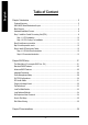
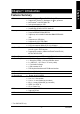
English Table of Content Chapter 1 Introduction ................................................................................................ 5 Features Summary ..............................................................................................................................5 8S651M-RZ Series Motherboard Layout ............................................................................................7 Block Diagram ...........................................................................
English Chapter 1 Introduction Features Summary CPU Chipset Memory Slots On-Board IDE — — — — — — — — — — — — — — — Socket 478 for Intel® M icro FC-PGA2 Pentium ® 4 processor Support Intel® Pentium ® 4 (Northwood, 0.13 m) processor Intel Pentium ® 4 400/533 M Hz FSB 2nd cache depends on CPU North Bridge:SiS 651 South Bridge:SiS 962L MuTIOL Media I/O 2 184-pin DDR sockets Supports DDR200/DDR266/DDR333 Supports up to 2 un-buffer Double-sided DIMM DDR200/266 /333 Supports up to 2GB (Max) Supports only 2.
English Hardware M onitor Additional Features Form Factor — — — — — — — — — — — — CPU/System Fan Revolution detect CPU/System Fan Control CPU Overheat Warning System Voltage Detect PS/2 Keyboard power on by password PS/2 Mouse power on STR(Suspend-To-RAM) AC Recovery USB KB/M ouse wake up from S3 Supports EasyTune 4 Supports @BIOS 24.4cm x 21.5cm M icro ATX size form factor, 4 layers PCB. Please set the CPU host frequency in accordance with your processor's specifications.
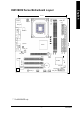
English 8S651M-RZ Series Motherboard Layout 21.5 cm A TX_12V COMA USB_LAN * ATX FDD RTL820 1 * F_AU DIO SiS 651 24.4 cm 8S651M-RZ VGA LPT SOC KET478 GAME IDE2 DDR2 AGP SUR_CEN IDE1 CD_I N DDR1 MIC_IN LINE_OUT LINE_IN DIMM _LED CPU_FAN KB_MS PCI1 W83697HF CODEC SiS 962L PCI2 PCI3 BAT CI SYS _FAN IR CLR_CMOS F_PANEL -C BIOS SPDI F_IO COMB F_U SB2 F_U SB1 PWR_LE D “* ”For 8S651M-RZ only.
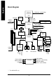
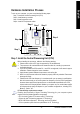
Pentium 4 Socket 478 CPU AGP 2X/4X AGPCLK (66MHz) CPUCLK+/- (100/133 MHz) System Bus 400/533 MHz VGA Port DDR SiS 651 200/266/333MHz ZCLK (66MHz) HCLK+/- (100/133 MHz) RJ45 3 PCI * 66 MHz 33 MHz 14.318 MHz 48 MHz RTL8201 * BIOS SiS 962L AC97 Link Game Port LPC BUS W83697HF Floppy LPT Port AC97 CODEC LINE-OUT PCICLK (33MHz) MIC LINE-IN English Block Diagram PCICLK (33MHz) USBCLK (48MHz) 14.
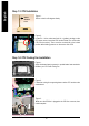
English Hardware Installation Process To set up your computer, you must complete the following steps: Step 1- Install the Central Processing Unit (CPU) Step 2- Install mem ory modules Step 3- Install expansion cards Step 4- Install I/O Peripherals cables Step 4 Step 1 Step 2 Step 4 Step 4 Step 3 Step 1: Install the Central Processing Unit (CPU) Before installing the processor, adhere to the following warning: 1. Please m ake sure the CPU type is supported by the m otherboard. 2.
English Step 1-1: CPU Installation Socket Actuation Lever Figure 1. Pull the rod to the 90-degree directly. Figure 2. Locate Pin 1 in the socket and look for a (golden) cut edge on the CPU upper corner. Insert the CPU into the socket. (Do not force the CPU into the socket.) Then m ove the socket lever to the locked position while holding pressure on the center of the CPU. Step 1-2: CPU Cooling Fan Installation Figure 1.
Before installing the m emory modules, adhere to the following warning: 1. When DIMM LED is ON, do not install / remove DIMM from socket. 2. Please note that the DIMM module can only fit in one direction due to the one notch. Wrong orientation will cause improper installation. Please change the insert orientation. The motherboard has 2 dual inline memory m odule (DIM M) sockets. The BIOS will automatically detects memory type and size.
English Step 3: Install expansion cards 1. Read the related expansion card's instruction document before install the expansion card into the com puter. 2. Please make sure your AGP card is AGP 4X/8X (1.5V). 3. Please carefully pull out the small white- drawable bar at the end of the AGP slot when you try to install/ Uninstall the AGP card. Please align the AGP card to the onboard AGP slot and press firmly down on the slot .M ake sure your AGP card is locked by the sm all white- drawable bar.
Monitor can be connected to VGA port. { Game/MIDI port This connector supports joystick, M IDI keyboard and other relate audio devices. | Line Out jack Connect the stereo speakers or earphone to this connector. } Line In jack Devices like CD-ROM , walkm an etc. can be connect to Line In jack. ~ MIC In jack Microphone can be connect to MIC In jack. After installation of the audio driver, you are able to use 2/4/6-channel audio feature by software selection.
English 1) ATX_12V (+12V Power Connector) This connector (ATX _12V) suppliesthe CPU operation voltage (Vcore). If this " ATX_ 12V connector" is not connected, system cannot boot. 3 Pin No. 1 2 3 4 4 2 1 Definition GND GND +12V +12V 2) ATX (ATX Power) AC power cord should only be connected to your power supply unit after ATX power cable and other related devices are firmly connected to the mainboard. 11 20 Pin No. Definition 1 3.3V 2 3.3V 3 GND 4 VCC 5 GND 1 10 6 7 8 9 10 Pin No.
This connector allows you to link with the cooling fan on the system case to lower the system temperature. Pin No. 1 2 3 1 Definition GND +12V Sense 5) IDE1/ IDE2(IDE1/IDE2 Connector) Please connect first harddisk to IDE1 and connect CDROM to IDE2. The red stripe of the ribbon cable must be the same side with the Pin1. 40 39 2 1 IDE2 IDE1 6) FDD (Floppy Connector) Please connect the floppy drive ribbon cables to FDD. It supports 360K,720K,1.2M,1.44M and 2.88M bytes floppy disk types.
English 7) DIMM_LED Do not remove memory modules while DIMM LED is on. It might cause short or other unexpected damages due to the 2.5V stand by voltage. Remove m emory m odules only when AC Power cord is disconnected. + - 8) F_PANEL (2x10 pins connector) Please connect the power LED, PC peaker, reset switch and power switch etc of your chassis front panel to the F_PANEL connector according to the pin assignment above.
PWR_LED is connect with the system power indicator to indicate whether the system is on/off. It will blink when the system enters suspend mode. If you use dual color LED, power LED will turn to another color. Pin No. 1 2 3 1 Definition MPD+ MPDMPD- 10) BAT (Battery) + CAUTION Danger of explosion if battery is incorrectly replaced. Replace only with the sam e or equivalent type recommended by the manufacturer. Dispose of used batteries according to the manufacturer's instructions.
English 11) F_AUDIO (F_AUDIO Connector) If you want to use Front Audio connector, you must remove 5-6, 9-10 Jumper. In order to utilize the front audio header, your chassis must have front audio connector. Also please make sure the pin assigment on the cable is the same as the pin assigment on the MB header. To find out if the chassis you are buying support front audio connector, please contact your dealer.
The SPDIF output is capable of providing digital audio to external speakers or compressed AC3 data to an external Dolby Digital Decoder. Use this feature only when your stereo system has digital input function. Use SPDIF IN feature only when your device has digital output function. Be careful with the polarity of the SPDIF_IO connector.
English 17) COMB (COM B Connector) Be careful with the polarity of the COMB connector. Check the pin assignm ent while you connect the COMB cable. Please contact your nearest dealer for optional COMB cable. 2 10 1 9 Pin No. 1 2 3 4 5 6 7 8 9 10 Definition NDCDBNSINB NSOUTB NDTRBGND NDSRBNRTSBNCTSBNRIBNoPin 18) CI (CASE OPEN) This 2 pin connector allows your system to enable or disable the "case open" item in BIOS if the system case begin rem ove. Pin No.
BIOS Setup is an overview of the BIOS Setup Program. The program that allows users to modify the basic system configuration. This type of inform ation is stored in battery-backed CMOS RAM so that it retains the Setup information when the power is turned off. ENTERING SETUP Powering ON the com puter and pressing immediately will allow you to enter Setup. If you require m o re adv anc ed BIO S s ettin gs, pl eas e g o to " Adv anc ed BIO S" se tti ng m en u.
English If you can't find the setting you want, please press "Ctrl+F1" to search the advanced option hidden. • Standard CMOS Features This setup page includes all the item s in standard com patible BIOS. • Advanced BIOS Features This setup page includes all the items of Award special enhanced features. • Integrated Peripherals This setup page includes all onboard peripherals. • Power Management Setup This setup page includes all the items of Green function features.
CMOS Setup Utility-Copyright (C) 1984-2004 Award Software Standard CMOS Features } } } } Date (mm:dd:yy) Time (hh:mm:ss) Fri, Jan 9 2004 22:31:24 IDE IDE IDE IDE [None] [None] [None] [None] Primary Master Primary Slave Secondary Master Secondary Slave Drive A Drive B Floppy 3 Mode Suport [1.44M, 3.
English Drive A / Drive B The category identifies the types of floppy disk drive A or drive B that has been installed in the com puter. None No floppy drive installed 360K, 5.25" 5.25 inch PC-type standard drive; 360K byte capacity. 1.2M, 5.25" 5.25 inch AT-type high-density drive; 1.2M byte capacity (3.5 inch when 3 M ode is Enabled). 720K, 3.5" 3.5 inch double-sided drive; 720K byte capacity 1.44M, 3.5" 3.5 inch double-sided drive; 1.44M byte capacity. 2.88M, 3.5" 3.5 inch double-sided drive; 2.
CMOS Setup Utility-Copyright (C) 1984-2004 Award Software Advanced BIOS Features First Boot Device Second Boot Device Third Boot Device Boot Up Floppy Seek [Floppy] [HDD-0] [CDROM] [Disabled] Item Help Menu Level} Select Boot Device priority Password Check [Setup] [Floppy] Boot from floppy [LS120] Boot from LS120 [HDD-0] Boot from First HDD [HDD-1] Boot from Second HDD higf : Move Enter: Select F5: Previous Values +/-/PU/PD: Value F10: Save F6: Fail-Save Default ESC: Exit F1: General Help F7: Optimi
English Integrated Peripherals CMOS Setup Utility-Copyright (C) 1984-2004 Award Software Integrated Peripherals IDE1 Conductor Cable IDE2 Conductor Cable On-Chip Primary PCI IDE On-Chip Secondary PCI IDE AC97 Audio Onboard LAN Device (* ) System Share Memory Size USB Controller USB Legacy Support Init Display First Onboard Serial Port A Onboard Serial Port B Serial Port B Mode Onboard Parallel Port Parallel Port Mode x EPP Mode Select ECP Mode Use DMA Game Port Address Midi Port Address Midi Port IRQ higf
Enabled Disabled (*) English Onboard LAN Device Enable onboard LAN device. (Default value) Disable onboard LAN device. System Share Memory Size 4MB/8MB/16MB/32MB/64MB Set onchip VGA shared memory size.(Default Value:32MB) USB Controller Enabled Disabled Enable USB Controller. (Default value) Disable USB Controller. USB Legacy Support Enabled Disabled Enable USB Legacy Support. Disable USB Legacy Support. (Default value) Init Display First AGP PCI Set Init Display First to AGP.
English Parallel Port Mode SPP EPP ECP ECP+EPP Using Parallel port as Standard Parallel Port. Using Parallel port as Enhanced Parallel Port. Using Parallel port as Extended Capabilities Port. (Default Value) Using Parallel port as ECP & EPP mode. EPP Mode Select EPP 1.9 EPP 1.7 Compliant with EPP 1.9 version. Com pliant with EPP 1.7 version.(Default Value) ECP Mode Use DMA 3 1 Set ECP Mode Use DMA to 3. (Default Value) Set ECP Mode Use DMA to 1.
S1(POS) S3(STR) English ACPI Suspend Type Set ACPI suspend type to S1. (Default Value) Set ACPI suspend type to S3. Soft-off by PWR_BTTN Off Suspend The user press the power button once, he can turn off the system. (Default Value) The user press the power button once, then the system will can enter suspend mode. System after AC Back LastState Off On When AC-power back to the system , the system will return to the Last state before AC-power off.
English Power LED in S1 state Blinking Dual/OFF In standby mode(S1), power LED will blink. (Default Value) In standby mode(S1): a. If use single color LED, power LED will turn off. b. If use dual color LED, power LED will turn to another color.
English PCI Health Status CMOS Setup Utility-Copyright (C) 1984-2004 Award Software PC Health Status Reset Case Open Status Case Opened VCORE +3.3V +5V +12V Current System Temperature Current CPU Temperature Current CPU FAN Speed Current SYSTEM FAN Speed CPU Warning Temperature CPU FAN Fail Warning SYSTEM FAN Fail Warning higf : Move Enter: Select F5: Previous Values [Disabled] No 1.71V 3.29V 4.99V 11.
English SYSTEM FAN Fail Warning Disabled Enabled Fan Warning Function Disable. (Default value) Fan Warning Function Enable.
English AGP Clock (MHz) Please set AGP Clock according to your requirem ent. Incorrect using it may cause your system broken. For power End-User use only! PCI Clock (MHz) Please set PCI Clock according to your requirem ent. Incorrect using it may cause your system broken.
English Load Optimized Defaults CMOS Setup Utility-Copyright (C) 1984-2004 Award Software } Standard CMOS Features Top Performance } Advanced BIOS Features Load Fail-Safe Defaults } Integrated Peripherals Load Optimized Defaults } } Power Management Setup PnP/PCI Configurations Set Supervisor Password Load Optimized Defaults Set(Y/N)? User Password N } PC Health Status } Frequency/Voltage Control Save & Exit Setup Exit Without Saving higf : Select Item ESC: Quit F8: Q-Flash F10: Save & Ex
English Save & Exit Setup CMOS Setup Utility-Copyright (C) 1984-2004 Award Software } Standard CMOS Features Top Performance } Advanced BIOS Features Load Fail-Safe Defaults } } Integrated Peripherals Power Management Setup Load Optimized Defaults Set Supervisor Password } PnP/PCI Configurations } PC Health Status } Frequency/Voltage Control Save to CMOS and EXITSet (Y/N)? User YPassword Save & Exit Setup Exit Without Saving higf : Select Item F10: Save & Exit Setup ESC: Quit F8: Q-Flash S
English Revision Chapter History 3 Install Drivers Install Drivers Pictures below are shown in Windows XP Insert the driver CD-title that came with your motherboard into your CD-ROM drive, the driver CD-title will auto start and show the installation guide. If not, please double click the CD-ROM device icon in "My com puter", and execute the setup.exe. INSTALL CHIPSET DRIVER This page shows the drivers that need to be installed for the system .
Item Description n SiS 650/650GL/650GX/651 VGA Driver VGA driver for VGA integrated SiS 650/650GL/650GX/651chipset. n USB Patch for WinXP This patch driver can help you to resolve the USB device wake up S3 hang up issue in XP. n SiS PCI Lan Driver ( * ) SiS 962L/963L LAN driver. n RealTek AC97 Audio Driver Install RealTek AC97 audio driver. n SIS USB 2.0 Driver It is recomm ended that you use the Microsoft Windows update for the most updated driver for XP/2K. If your CD doesn't have SiS® USB2.
English 8S651M-RZ Series Motherboard - 38 -
English - 39 - Driver Installation
English CONTACT US Contact us via the information in this page all over the world. — Taiwan Gigabyte TechnologyCo., Ltd. Address: No.6, Bau Chiang Road, Hsin-Tien, Taipei Hsien, Taiwan,R.O.C. Tel: 886 (2) 8912-4888 Fax: 886 (2) 8912-4004 Tech.Support: http://tw.giga-byte.com/TechSupport/ServiceCenter.htm Non-Tech.Support (Sales/Marketing issues): http://ggts.gigabyte.com.tw/nontech.asp Website: http://www.gigabyte.com.tw — USA G.B.T. INC. Address: 17358 Railroad St, City of Industry, CA 91748.