Intel® Digital Set Top Box Display Driver User’s Guide for Microsoft* Windows* CE 5.
Legal Statements INFORMATION IN THIS DOCUMENT IS PROVIDED IN CONNECTION WITH INTEL PRODUCTS. NO LICENSE, EXPRESS OR IMPLIED, BY ESTOPPEL OR OTHERWISE, TO ANY INTELLECTUAL PROPERTY RIGHTS IS GRANTED BY THIS DOCUMENT.
Contents 1 Introduction ............................................................................................................. 7 1.1 2 Definitions ....................................................................................................................................... 7 Feature Summary .................................................................................................... 8 2.1 GMCHs .......................................................................................
5.2 Configuration Changes................................................................................................................. 24 5.2.1 Changing the TV Format to PAL-B........................................................................................ 24 5.2.2 Changing the TV Output Type to Component....................................................................... 24 5.2.3 Enabling 3D Support ..............................................................................................
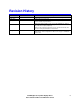
Revision History Date Driver May 2005 18 May 2005 July 2005 1-0-0-0064 December 2005 1-0-0-0092 January 2006 1-0-0-0094 Description This is the first version of the new guide. The content and layout are all new. Updated after technical review. Added hardware-accelerated bob support for overlay surfaces with interleaved data using DirectDraw. Added new samples (BobTest, CapsTest, PerPixelAlphaBltTest, VBITest). Updated escape interface for HDMI Hotplug and HDMI/siI9030 over scan flag.
This page intentionally left blank 6 Intel® Digital Set Top Box Display Driver User’s Guide for Microsoft* Windows* CE 5.
1 Introduction This document describes the Intel® Digital Set Top Box Display Driver for Microsoft* Windows* CE 5.0. It provides a summary of display driver features, installation notes, and configuration information. It is targeted at all platform and system developers who need to interface with the graphics subsystem. This includes, but is not limited to: platform designers, system BIOS developers, system integrators, original equipment manufacturers, and system control application developers. 1.
2 Feature Summary 2.1 GMCHs The Intel® Digital Set Top Box Display Driver supports the following Graphic Memory Controller Hubs: • • Intel® 82830M GMCH Intel® 82854 GMCH 2.1.1 Base Features 2.1.1.1 Common Base Features The Intel® Digital Set Top Box Display Driver includes support for: • • • • • • • 8 DirectDraw 2D APIs, including: DdCreateSurface, DdDestroySurface, DdLock, DdBlt and DdAlphaBlt, and DdUnlock.
2.1.2 830 and 854 Base Features The Intel® Digital Set Top Box Display Driver for the 830 and 854 includes support for: • • • • • • • • 2.2 Region alpha blending using the DirectDraw method AlphaBlt — where a single alpha value is used for the entire rectangle. Per-pixel alpha blending using the DirectDraw method AlphaBlt — where a separate alpha value is used for each pixel. Plane based alpha blending, which uses the GMCH to blend the graphics plane with the overlay plane.
2.3 Display Configuration The display driver includes support for the following resolutions. (In the following list 60Hz is used as a short-hand for 59.94Hz.
2.3.1 Display Configuration Notes Note: The TV Format and resolution cannot be changed at run-time. Any changes must be made in the video.reg registry file. Note: Expect TVs to crop the desktop as TVs normally crop their output. Monitors that are normally attached to PCs are not likely to crop the desktop. Monitors accepting TV input may crop the desktop. For that reason, avoid placing user interface elements near the edge of the display.
3 Installation Notes 3.1 Display Driver MSI The display driver MSI installs driver files to the $(_WINCEROOT)\IntelCEG\Drivers\Display directory. 3.1.1 830 MSI The 830 MSI installs the display driver DLL, the display driver D3D Mobile DLL, video.reg, the Conexant cx873 DLL, and the Focus fs454 DLL to the I830 subdirectory. It installs display driver include files to the I830\extras\src\inc subdirectory.
3.2 Driver Files The display driver and TV encoder DLLs must be included in the Windows CE image. To do this, make sure either Platform.bib or Project.bib includes statements for the display driver DLL and the TV encoder DLL. A Direct3D Mobile implementation module can be included optionally For example, to configure the display driver and the Focus FS454 DLL: #define INTELCEG_DRIVERS_DIR $(_WINCEROOT)\INTELCEG\drivers ddi_iceg.dll $(INTELCEG_DRIVERS_DIR)\display\i854\ddi_iceg.dll fs454.
4 Configuration Information The display driver and TV Encoder DLL configuration use registry settings found in video.reg. The following sections describe the available options. This section is a companion to, and not a replacement for, video.reg. See video.reg for acceptable values and default values for each of the options described below. 4.1 Display Driver Options 4.1.1 Display Options The display options configure the display resolution and mode.
AlphaBlendMode This key is used to enable ARGB32 pixel format on the framebuffer. When in this mode, the alpha channel in the frame buffer is used by the HW internally to blend the graphics plane over the video overlay plane. The value for this registry key can be either 0: disabled, or 1: enabled. Notes: • • • • This feature is only supported with the “Depth” registry key set to 0x20 (32). It is ignored otherwise.
4.1.2 Port Driver (TV Encoder DLL) Options The port driver (TV encoder DLL) options control the selection of the port driver and the discovery of the TV encoder device. I2cPin This setting selects the I2C* bus. (Value of 1 usually identifies DVO-A, 4 usually identifies DVO-B/C) I2cDab This setting selects the Data Address Byte (DAB) for the TV encoder silicon in the system. The DAB is normally specified by the port driver itself, but this setting allows for customization if needed.
4.1.3 Memory Management Options The memory management options control memory management code. [HKEY_LOCAL_MACHINE\Drivers\Display\Intel] MaxFbSize This key controls the size of the frame buffer in bytes. 830, 854: To compute the frame buffer size required for a given resolution, first compute the width in bytes using the width * bytes per pixel. Then, if that isn't a power of two raise it to the next power of two to get the stride. Finally, compute the total size as stride * height.
4.1.4 2D Graphics Options The display driver support options to control 2D rendering. Some of these also affect video rendering. [HKEY_LOCAL_MACHINE\Drivers\Display\Intel] SysToVidStretch This key determines if the system to video stretch BLT functionality is enabled in the driver. 0 = disabled 1 = enabled BlendFilter This key determines the blending filter used for 2D stretch BLTs via GDI stretch BLT and DirectDraw AlphaBlt routines.
4.1.5 GDI Options The following option is a GDI option that indirectly affects the display driver. The display driver does not read this key. Instead, it affects how GDI calls the display driver. For more information, search for “ForceGRAY16” on www.microsoft.com\msdn. [HKEY_LOCAL_MACHINE\System\GDI] ForceGRAY16 This key controls GDI anti-aliasing. 4.1.6 Video Options The display driver supports a number of options to control video rendering.
4.1.7 Direct3D Mobile Options Direct 3D Mobile is supported on the 830 and 854. [HKEY_LOCAL_MACHINE\System\D3DM\Drivers] RemoteHook This is set to “ddi_iceg” to inform GWES which driver to request Direct3D Mobile support from. Leaving this blank will disable Direct3D Mobile in the operating system. [HKEY_LOCAL_MACHINE\Drivers\Display\Intel] Enable3D This setting enables or disables 3D support in the display driver. 0 disables support, 1 enables support.
4.2 Port Driver (TV Encoder DLL) Attributes Port driver (TV Encoder DLL) attributes are used if the display type is either DVO-only or Twin. In that case, the display driver reads port driver attribute settings from the registry, tests their values, and if they are valid, passes them to the port driver during initialization. Port driver attributes have Boolean, range, String, or list types. Boolean attributes values must be 0 or 1.
4.2.2.1 DAC setting with different TV Output Type on HH2 Currently there is a new video card named “Hominy Hill2” that uses the CX25899 as the TV encoder. There are four analog outputs on that card, which can be configured to different signals in order to adapt to the different TV Output Types. In video.reg, there are 4 parameters for analog output’s setting, “DACA, DACB, DACC, DACD”.
5 Configuration The display driver release includes a video.reg configuration file modified to run with the target platform’s default configuration. 5.1 Default Configuration The configuration file video.reg is designed to work without changes in the following default configurations. 5.1.1 • • • • • • • 5.1.
5.2 Configuration Changes The following sections describe how to change the video.reg configuration file to accomplish some common configuration changes. 5.2.1 Changing the TV Format to PAL-B To change the TV format to PAL-B, do the following: 1. First, change the frame buffer to 720x576@50. • • Leave the width at 720 Change the height setting to 576 o "Height"=dword:240 Change the refresh setting to 50 o "Refresh"=dword:32 • 2.
5.2.
6 Hardware Limitations 6.1 830 Chipset Limitations • • YUV 4:2:0 planar format overlay surfaces, that contain interleaved data, are displayed with the temporal chroma artifact, which is commonly referred to as the Chroma Upsampling Error (CUE). Both interleaved and progressive data are supported by the YUV 4:2:2 packed and xRGB formats. 6.
7 Programming Interface 7.1 WinCE Graphics Driver Escape Interface The Intel® Digital Set Top Box Graphics Driver for Microsoft Windows CE .NET 4.2/5.0 supports the WinCE system API - ExtEscape(), which provides a dynamic configuration channel to the display driver. Following shows the ExtEscape API function prototype and the usage module for the user application to communicate with the display driver.
Following is a summary of the escape codes supported by the display driver. Please refer to icegd_public_escape.h for more details.
7.1.1.1 ICEGD_ESCAPE_ENABLE_PORT Input Data Structure Output Data Structure Notes esc_port_ctrl_t port options: 0 – Primary Display 1 – Secondary Display esc_port_ctrl_t esc_status_t esc_port_ctrl_t enable options: 0 – disable 1 – enable esc_status_t status options: 0 – ESCAPE_STATUS_NOERROR 1 – ESCAPE_STATUS_ERROR Description This escape code is used to enable/disable primary/secondary display port.
7.1.1.2 ICEGD_ESCAPE_GET_NUM_PD_ATTRIBUTES Input Data Structure N/A Output Data Structure int Notes Must be used before a call to ICEGD_ESCAPE_GET_AVAIL_PD_ATTRIBUTES to size the required igd_attr_t data structure array. Description This escape code is used to request the total number of attributes supported by the Port Driver, which will be used by ICEGD_ESCAPE_GET_AVAIL_PD_ATTRIBUTES to calculate the size of the buffer for the attribute list.
7.1.1.3 ICEGD_ESCAPE_GET_AVAIL_PD_ATTRIBUTES Input Data Structure N/A Output Data Structure A buffer pointed by igd_attr_t* Notes All structures below should be with same size and should be converted to others according to the attribute type.
7.1.1.4 ICEGD_ESCAPE_SET_PD_ATTRIBUTES Input Data Structure igd_attr_t Output Data Structure N/A Notes Only a single attribute can be set per call. Description This escape code is used to set Port Driver attributes. It is always called after the attribute list filled by ICEGD_ESCAPE_GET_AVAIL_PD_ATTRIBUTES. The attribute list is different between different cards.
int number;//available attributes number igd_attr_t *attr_list, *current; /*other types such as igd_list_attr_t, igd_bool_attr_t, igd_string_attr_t can refer to the implement of igd_range_attr_t as below*/ igd_range_attr_t *range; //(1) esc_status_t status; ExtEscape( Hdc, ICEGD_ESCAPE_GET_NUM_PD_ATTRIBUTES, 0, NULL, sizeof(unsigned int), (LPSTR)&number); //the attribute list should contain number entries of igd_attr_t.
7.1.1.5 ICEGD_ESCAPE_SET_OVL_COLOR_PARAMS Input Data Structure esc_color_params_t Output Data Structure N/A Notes esc_color_params flag options: Optional: GAMMA_FLAG (0x1) BRIGHTNESS_FLAG (0x2) CONTRAST_FLAG (0x4) SATURATION_FLAG (0x8) Mandatory: OVL_COLOR_FLAG (0x10) Description This escape code is used to set overlay attributes (brightness, contrast, saturation, and gamma). Please make sure that OVL_COLOR_FLAG should always be set. The sample affect only when using overlay.
7.1.1.6 ICEGD_ESCAPE_SET_FB_GAMMA_RAMP Input Data Structure esc_color_params_t Output Data Structure N/A Notes esc_color_params flag options: Mandatory: GAMMA_FLAG (0x1) Not Applicable: BRIGHTNESS_FLAG (0x2) CONTRAST_FLAG (0x4) SATURATION_FLAG (0x8) OVL_COLOR_FLAG (0x10) Description This escape code is used to set frame buffer gamma correction ramp. Legal values are from 1-500, 1 - default, 500 – brightest.
7.1.1.7 ICEGD_ESCAPE_GET_MEM_STATS Input Data Structure N/A Output Data Structure esc_mem_stats_t Description This escape code is used to get memory statistics. Output Data Structure Definition Please refer to igd_public.h for details about data structure esc_mem_stats_t.
7.1.1.8 ICEGD_ESCAPE_GET_MONITOR_DESC Input Data Structure Int Output Data Structure esc_monitor_desc_t Notes The input is port number, which can be only 0 or 1. Description This escape code is used to get the monitor description (EDID). Output Data Structure Definition Please refer to icegd_public_escape.h for details about data structure esc_monitor_desc_t.
7.1.1.9 ICEGD_ESCAPE_VBI_ENABLE Input Data Structure N/A Output Data Structure Notes N/A Description This escape code is used to call port driver to enable Line 21 VBI (Vertical Blank Interrupt) data. It is always used before ICEGD_ESCAPE_VBI_UPDATE with ICEGD_ESCAPE_VBI_DISABLE following. Example ExtEscape( Hdc, ICEGD_ESCAPE_VBI_ENABLE, 0, NULL, 0, NULL ); 38 Intel® Digital Set Top Box Display Driver User’s Guide for Microsoft* Windows* CE 5.
7.1.1.10 ICEGD_ESCAPE_VBI_DISABLE Input Data Structure N/A Output Data Structure Notes N/A Description This escape code is used to call port driver to disable Line 21 VBI (Vertical Blank Interrupt) data. It is always used after ICEGD_ESCAPE_VBI_UPDATE finished. Example ExtEscape( Hdc, ICEGD_ESCAPE_VBI_DISABLE, 0, NULL, 0, NULL ); Intel® Digital Set Top Box Display Driver User’s Guide for Microsoft* Windows* CE 5.
7.1.1.11 ICEGD_ESCAPE_VBI_UPDATE Input Data Structure vbi_data Output Data Structure Notes N/A Description This escape code is used to call port driver to update VBI. It passes VBI line information to the TV encoder to insert into the analog TV signal. Before you update VBI, you should enable VBI, and disable VBI after the update has completed. There should be a short wait between every update operation. Input Data Structure Definition Please refer to igd_public.h for vbi data structure details.
ExtEscape( Hdc, ICEGD_ESCAPE_VBI_UPDATE, sizeof(vbi_data) + 2, (const char*)pvbi, 0, NULL); Sleep(33); } Sleep(1000); //erase cc displayed memory pvbi->pucData[ 0 ] = 0x14; pvbi->pucData[ 1 ] = 0x2c; ExtEscape( Hdc, ICEGD_ESCAPE_VBI_UPDATE, sizeof(vbi_data) + 2, (const char*)pvbi, 0, NULL); Sleep(33); //disable vbi ExtEscape( Hdc, ICEGD_ESCAPE_VBI_DISABLE, 0, NULL, 0, NULL ); free( pvbi ); Intel® Digital Set Top Box Display Driver User’s Guide for Microsoft* Windows* CE 5.
7.1.1.12 ICEGD_ESCAPE_INTERRUPT_INSTALL Input Data Structure escape_interrupt_data Output Data Structure N/A Notes ESCAPE_INTERRUPT_VBLANK = 0x1000 Description This escape code is used to install an interrupt. It is always followed by ICEGD_ESCAPE_INTERRUPT_UNINSTALL. unInterrupt of the input structure could only be ESCAPE_INTERRUPT_VBLANK. After the operation finishes, hWaitObject will return a handle to the OS dependent wait object. Input Data Structure Definition Please refer icegd_public_escape.
7.1.1.13 ICEGD_ESCAPE_INTERRUPT_UNINSTALL Input Data Structure Escape_interrupt_data Output Data Structure Notes N/A Description This escape code is used to un-install an interrupt. Example escape_interrupt_data interrupt; memset(&interrupt, 0, sizeof(escape_interrupt_data)); interrupt.
7.1.1.14 ICEGD_ESCAPE_SET_VIDEO_PLANE_ZORDER Input Data Structure esc_vid_plane_zorder_t Output Data Structure N/A Notes IGD_ZORDER_OVERLAY_ABOVE_PLANE IGD_ZORDER_OVERLAY_BELOW_PLANE Description This escape code is used to set Z-order and key color for plane based alpha support. Input Data Structure Definition Please refer to icegd_public_escape.
7.1.1.15 ICEGD_ESCAPE_SET_HW_ALPHA_COMPAT_MODE Input Data Structure Int Output Data Structure N/A Notes Input can be only : HW_ALPHA_COMPAT_VIDEO_RENDERER_MODE 0x00000001 Description This escape code is used to enable the HW plane alpha mode. Example int mode; mode = HW_ALPHA_COMPAT_VIDEO_RENDERER_MODE; ExtEscape( Hdc, ICEGD_ESCAPE_SET_HW_ALPHA_COMPAT_MODE, sizeof(char), (LPCSTR)&mode, 0, NULL); Intel® Digital Set Top Box Display Driver User’s Guide for Microsoft* Windows* CE 5.
7.1.1.16 ICEGD_ESCAPE_DRIVER_VERSION Input Data Structure N/A Output Data Structure esc_driver_version_t Description This escape code is used to get the driver version. Input Data Structure Definition Please refer to icegd_public_escape.
7.1.1.17 ICEGD_ESCAPE_I2C_CONFIG Input Data Structure esc_i2c_config_t Output Data Structure Notes N/A Description This escape code is used before ICEGD_ESCAPE_I2C_ACCESS to configure Pin Pair, DAB and I2C speed. Example See ICEGD_ESCAPE_I2C_ACCESS for a complete I2C example. Intel® Digital Set Top Box Display Driver User’s Guide for Microsoft* Windows* CE 5.
7.1.1.18 ICEGD_ESCAPE_I2C_ACCESS Input Data Structure esc_i2c_access_t Output Data Structure unsigned char Notes In case of read operation, data is returned in output buffer. Write operation data is retrieved from the esc_i2c_access_t input buffer. Description This escape code is used to access I2C. It can implement a read or write operation by setting the mode. Input Data Structure Definition Please refer icegd_public_escape.
/* Read the data to make sure the last step works ok */ i2c_access.mode = INTEL_I2C_MODE_READ; ExtEscape( Hdc, ICEGD_ESCAPE_I2C_ACCESS, sizeof(esc_i2c_access_t), (LPCSTR)&i2c_access, sizeof(unsigned char), (LPSTR)&data2); printf("%d\n", data2); Intel® Digital Set Top Box Display Driver User’s Guide for Microsoft* Windows* CE 5.
7.1.1.19 ICEGD_ESCAPE_MULT_DVO_SELECT Input Data Structure Esc_mult_dvo_select_t Output Data Structure N/A Notes @select: ESC_MULT_DVO_MASTER : multiplex DVO master port (DVOB) ESC_MULT_DVO_SLAVE : slave port (DVOC) @flag: User need to set additional flag for the HDMI output on SD ESC_DISPLAY_PIXEL_DOUBLE ESC_DISPLAY_INTERLACED Description This escape code is used to select a DVO port (master/slave). Input Data Structure Definition Set select to select a DVO port.
7.1.1.20 ICEGD_ESCAPE_QUERY_HDMI_HOTPLUG Input Data Structure N/A Output Data Structure esc_enum_hotplug_status Notes ESC_HDMI_PLUG_IN : ESC_HDMI_PLUG_OUT Description This escape code is used to query the HDMI hotplug status. Output Data Structure Definition If the HDMI is plugged in, return ESC_HDMI_PLUG_IN, else, return ESC_HDMI_PLUG_OUT.
7.1.1.21 ICEGD_ESCAPE_WAIT_HDMI_HOTPLUG Input Data Structure N/A Output Data Structure esc_enum_hotplug_status Notes ESC_HDMI_PLUG_IN : ESC_HDMI_PLUG_OUT Description This escape code is used to wait for an HDMI hotplug event. Output Data Structure Definition Block the user thread until the HDMI is plugged in, then return ESC_HDMI_PLUG_IN, or plugged out, then return ESC_HDMI_PLUG_OUT.
7.1.1.22 ICEGD_ESCAPE_SET_SCAN_INFO Input Data Structure Int Output Data Structure N/A Notes N/A Description This escape code is used to set the HDMI scan info. Input Data Structure Definition The input data can be set between 0-3. But only 1 and 2 make sense now. 1—overscanned, 2—underscanned.