
32-Bit High-Performance Superscalar Processor Data Sheet

80960HA/HD/HT
18 Datasheet
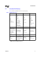
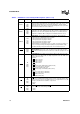
HOLD
I
S(L)
HOLD REQUEST signals that an external agent requests access to the
processor’s address, data, and control buses. When HOLD is asserted, the
processor:
Completes the current bus request.
Asserts HOLDA and floats the address, data, and control buses.
When HOLD is deasserted, the HOLDA pin is deasserted and the processor
reassumes control of the address, data, and control pins.
HOLDA
O
H(1)
B(0)
R(Q)
HOLD ACKNOWLEDGE indicates to an external master that the processor has
relinquished control of the bus. The processor grants HOLD requests and enters
the HOLDA state while the RESET
pin is asserted.
HOLDA is never granted while LOCK
is asserted.
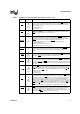
BOFF
I
S(L)
BUS BACKOFF forces the processor to immediately relinquish control of the bus
on the next clock cycle. When READY
/BTERM is enabled and:
When BOFF
is asserted, the address, data, and control buses are floated on the
next clock cycle and the current access is aborted.
When BOFF
is deasserted, the processor resumes by regenerating the aborted
bus access.
See
Figure 16 on page 48 for BOFF
timing requirements.
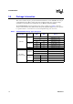
BREQ
O
H(Q)
B(Q)
R(0)
BUS REQUEST indicates that a bus request is pending in the bus controller.
BREQ does not indicate whether or not the processor is stalled. See BSTALL for
processor stall status. BREQ may be used with BSTALL to indicate to an external
bus arbiter the processor’s bus ownership requirements.
BSTALL
O
H(Q)
B(Q)
R(0)
BUS STALL indicates that the processor has stalled pending the result of a
request in the bus controller. When BSTALL is asserted, the processor must
regain bus ownership to continue processing (i.e., it may no longer execute
strictly out of on-chip cache memory).
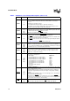
CT3:0
O
H(Z)
B(Z)
R(Z)
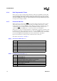
CYCLE TYPE indicates the type of bus cycle currently being started or processor
state. CT3:0 encoding follows:
Cycle Type ADSCT3:0
Program-initiated access using 8-bit bus 00000
Program-initiated access using 16-bit bus 00001
Program-initiated access using 32-bit bus 00010
Event-initiated access using 8-bit bus 00100
Event-initiated access using 16-bit bus 00101
Event-initiated access using 32-bit bus 00110
Reserved 00X11
Reserved for future products 01XXX
Reserved 1XXXX
XINT7:0
I
A(E)
A(L)
EXTERNAL INTERRUPT pins are used to request interrupt service. These pins
may be configured in three modes:
Dedicated Mode: Each pin is assigned a dedicated interrupt level. Dedicated
inputs may be programmed to be level (low or high) or edge (rising or falling)
sensitive.
Expanded Mode: All eight pins act as a vectored interrupt source. The interrupt
pins are level sensitive in this mode.
Mixed Mode: The XINT7:5
pins act as dedicated sources and the XINT4:0 pins
act as the five most significant bits of a vectored source. The least significant bits
of the vectored source are set to “010” internally.
NMI
I
A(E)
NON-MASKABLE INTERRUPT causes a non-maskable interrupt event to occur.
NMI
is the highest priority interrupt source. NMI is falling edge triggered.
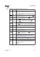
Table 7. 80960Hx Processor Family Pin Descriptions (Sheet 3 of 4)
Name Type Description