
Datasheet


PROCESSOR FEATURES
51
1. This is an 8-bit field. The device that sent the alert will respond to the ARA Packet with its address in the seven most
significant bits. The least significant bit is undefined and may return as a ‘1’ or ‘0’. See Section 5.2.7 for details on the
Thermal Sensor Device addressing.
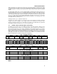
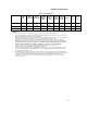
Table 41. Command Byte Bit Assignments
Register Command Reset State Function
RESERVED 00h N/A Reserved for future use
RRT 01h N/A Read processor core thermal data
RS 02h N/A Read status byte (flags, busy signal)
RC 03h 0000 0000 Read configuration byte
RCR 04h 0000 0010 Read conversion rate byte
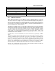
RESERVED 05h 0111 1111 Reserved for future use
RESERVED 06h 1100 1001 Reserved for future use
RRHL 07h 0111 1111 Read processor core thermal diode T
HIGH
limit
RRLL 08h 1100 1001 Read processor core thermal diode T
LOW
limit
WC 09h N/A Write configuration byte
WCR 0Ah N/A Write conversion rate byte
RESERVED 0Bh N/A Reserved for future use
RESERVED 0Ch N/A Reserved for future use
WRHL 0Dh N/A Write processor core thermal diode T
HIGH
limit
WRLL 0Eh N/A Write processor core thermal diode T
LOW
limit
OSHT 0Fh N/A One shot command (use send byte packet)
RESERVED 10h – FFh N/A Reserved for future use
All of the commands are for reading or writing registers in the thermal sensor except the one-shot command
(OSHT). The one-shot command forces the immediate start of a new conversion cycle. If a conversion is in
progress when the one-shot command is received, then the command is ignored. If the thermal sensor is in
standby mode when the one-shot command is received, a conversion is performed and the sensor returns to
standby mode. The one-shot command is not supported when the thermal sensor is in auto-convert mode.
If the thermal sensor is in auto-convert mode and is between conversions, then the conversion rate timer
resets, and the next automatic conversion takes place after a full delay elapses. The default command after
reset is to a reserved value (00h). After reset, receive byte packets will return invalid data until another
command is sent to the thermal sensor. This one-shot feature is currently susceptible to failure and should
not be used (i.e. don't issue one-shot commands) when in auto convert mode.
5.2.6 THERMAL SENSOR REGISTERS
5.2.6.1 Thermal Reference Registers
The processor core and thermal sensor internal thermal reference registers contain the thermal reference
value of the thermal sensor and the processor core thermal diodes. This value ranges from +127 to -128
decimal and is expressed as a two’s complement, eight-bit number. These registers are saturating, i.e. values
above 127 are represented at 127 decimal, and values below -128 are represented as -128 decimal.
5.2.6.2 Thermal Limit Registers
The thermal sensor has two thermal limit registers; they define high and low limits for the processor core
thermal diode. The encoding for these registers is the same as for the thermal reference registers. If the diode
thermal value equals or exceeds one of its limits, then its alarm bit in the Status Register is triggered.