
Datasheet


SIGNAL QUALITY
38
pads
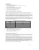
. Overshoot/Undershoot shown in Figure 14 is for illustrative purposes only to help explain Ringback and Settling
Limit. Refer to Figure 13 for an illustration of Overshoot/Undershoot specifications.
Undershoot
Overshoot
Settling Limit
Settling Limit
Rising-Edge
Ringback
Falling-Edge Ringback
V
LO
V
SS
Time
V =
HI
V
CC
2.5
Voltage
RINGBACK
Figure 14. Non-AGTL+ Overshoot/Undershoot, Settling Limit, and Ringback
4.3.1 2.5V Signal Overshoot/Undershoot Guidelines
The Overshoot/Undershoot guideline limits transitions beyond V
CC
or V
SS
due to fast signal edge rates. Refer to Figure
14 for an illustration of Overshoot/Undershoot specifications for non-AGTL+ signals. The processor may be damaged if
Overshoot/Undershoot specifications are not met. The Overshoot/Undershoot specification is shown in Table 26.
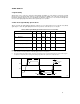
Table 27. 2.5V Tolerant Signal Group Overshoot/Undershoot at the Processor Core Pins
1,2,3,4,5,6,7,8,9
Overshoot/Undershoot Max Pulse Duration (nS)
Magnitude AF = 0.01 AF = 0.1 AF = 1
2.3 60 7.6 0.76
2.25 60 14.8 1.48
2.2 60 27.2 2.7
2.15 60 50 5
2.1 60 60 9.1
2.05 60 60 16.4
2.0 60 60 30
NOTES: