
Datasheet


SIGNAL QUALITY
33
4. Signal Quality
Signals driven on the system bus should meet signal quality specifications to ensure that the components read data
properly and to ensure that incoming signals do not affect the long-term reliability of the component. Specifications are
provided for simulation at the processor core. Meeting the specifications at the processor core in Table 21 through Table
27 ensures that signal quality effects will not adversely affect processor operation.
4.1 Bus Clock Signal Quality Specifications
Table 21 describes the signal quality specifications at the processor core pad for the processor system bus clock (BCLK)
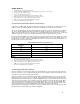
signal. Figure 11 shows the signal quality waveform for the system bus clock at the processor core pads.
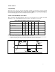
Table 21. BCLK Signal Quality Specifications at the Processor Core Pads
1
V# Parameter Min Nom Max Unit Figure Notes
V1: BCLK V
IL
-0.3 0.5
V 11
V2: BCLK V
IH
2.0
2.625 V 11
V3: V
IN
Absolute Voltage Range
–0.7 2.0 3.3 V 11
V4: Rising Edge Ringback
2.0
V 11 2
V5: Falling Edge Ringback
0.5
V 11 2
NOTES:
1. Unless otherwise noted, all specifications in this table apply to all processor frequencies.
2. The rising and falling edge ringback voltage specified is the minimum (rising) or maximum (falling) absolute voltage the BCLK signal
can dip back to after passing the V
IH
(rising) or V
IL
(falling) voltage limits. This specification is an absolute value.
V2
V1
V3
V3
T3
V5
V4
T6 T4 T5
000806
Figure 11. BCLK, TCK, PICCLK Generic Clock Waveform at the processor Core Pads