
Datasheet


Pentium
®
III Xeon™ Processor at 500 and 550 MHz
98
Datasheet
9.1.59 TMS (I)
The TMS (Test Mode Select) signal is a TAP support signal used by debug tools.
9.1.60 TRDY# (I)
The TRDY# (Target Ready) signal is asserted by the target to indicate that it is ready to receive a
write or implicit writeback data transfer. TRDY# must connect the appropriate pins of all Pentium
III
Xeon processor system bus agents.
9.1.61 TRST# (I)
The TRST# (Test Reset) signal resets the Test Access Port (TAP) logic. Pentium
III
Xeon
processors self-reset during power on; therefore, it is not necessary to drive this signal during
power on reset.
9.1.62 VID_L2[4:0], VID_CORE[4:0](O)
The VID (Voltage ID) pins can be used to support automatic selection of power supply voltages.
These pins are not signals, but are either an open circuit or a short circuit to V
SS
on the processor.
The combination of opens and shorts defines the voltage required by the processor. The VID pins
are needed to cleanly support voltage specification variations on Pentium
III
Xeon processors. See
Table 2 for definitions of these pins. The power supply must supply the voltage that is requested by
these pins, or disable itself. See Table 4 for the maximum rating for these signals.
9.1.63 WP (I)
WP (Write Protect) can be used to write protect the scratch EEPROM. A high level write-protects
the scratch EEPROM.
9.2 Signal Summaries
The following tables list attributes of the Pentium
III
Xeon processor output, input, and I/O signals.
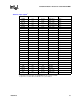
† Outputs are not checked in FRC mode.
Table 48. Output Signals
†
Name Active Level Clock Signal Group
FERR# Low Asynch CMOS Output
IERR# Low Asynch CMOS Output
PRDY# Low BCLK AGTL+ Output
SMBALERT# Low Asynch SMBus Output
TDO High TCK TAP Output
THERMTRIP# Low Asynch CMOS Output
VID_CORE[4:0] High Asynch Power/Other
VID_L2[4:0] High Asynch Power/Other