
Datasheet


Pentium
®
III Xeon™ Processor at 500 and 550 MHz
Datasheet
89
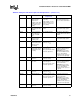
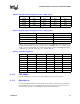
Table 46 gives the interconnect between the processor and bus signals for a 2-way system.
During power-up configuration, the central agent must assert its BR0# signal. All symmetric agents
sample their BR[3:0]# pins on active-to-inactive transition of RESET#. The pin on which the agent
samples an active level determines its agent ID. All agents then configure their BREQ[3:0]# signals
to match the appropriate bus signal protocol, as shown in Table 47.
9.1.14 CPU_SENSE
The CPU_SENSE pin is connected to the VCC_CORE power plane on the substrate.
9.1.15 D[63:00]# (I/O)
The D[63:00]# (Data) signals are the data signals. These signals provide a 64-bit data path between
the Pentium
III
Xeon processor system bus agents, and must connect the appropriate pins on all
such agents. The data driver asserts DRDY# to indicate a valid data transfer.
Table 45. BR[3:0]# Signals Rotating Interconnect, 4-Way System
Bus Signal Agent 0 Pins Agent 1 Pins Agent 2 Pins Agent 3 Pins
BREQ0# BR0# BR3# BR2# BR1#
BREQ1# BR1# BR0# BR3# BR2#
BREQ2# BR2# BR1# BR0# BR3#
BREQ3# BR3# BR2# BR1# BR0#
Table 46. BR[3:0]# Signals Rotating Interconnect, 2-Way System
Bus Signal Agent 0 Pins Agent 1 Pins
BREQ0# BR0# BR3#
BREQ1# BR1# BR0#
BREQ2# BR2# BR1#
BREQ3# BR3# BR2#
Table 47. Agent ID Configuration
BR0# BR1# BR2# BR3# A5# Agent ID
LH H HH0
HH H LH1
HH L HH2
HL H HH3
L H H H L 0(master)
H H H L L 0(checker
H H L H L 2(master)
H L H H L 2(checker