
Datasheet


Pentium
®
III Xeon™ Processor at 500 and 550 MHz
Datasheet
81
TDO 10 Test data output
signal from last
component in
boundary scan chain
of MP cluster to ITP;
test output is read
serially.
Add 150W pull-up resistor
(to V
CC
TA P
)
Design pull-ups to route
around empty processor
sockets (so resistors are
not in parallel)
Operates synchronously with
TCK. Each Pentium III Xeo
processor have a 25W driver.
DBINST# 11 Indicates to target
system that an ITP is
installed.
Add ~10 kW pull-up
resistor
Not required if boundary scan
is not used in target system.
TRST# 12 Test reset signal fro
ITP to MP cluster,
used to reset TAP
logic.
Add ~680W pull-down Asynchronous input signal.
To disable TAP reset if ITP not
installed.
BSEN# 14 Informs target system
that ITP is using
boundary scan.
Not required if boundary scan
is not used in target system.
PREQ0# 16 PREQ0# signal,
driven by ITP, makes
requests to P0 to
enter debug.
Add 150 to 330W pull-up
resistor (to V
CC
2.5
)
PRDY0# 18 PRDY0# signal,
driven by P0, informs
ITP that P0 is ready
for debug.
Te r m i n a t e
2
signal properly
at the debug port
Debug port must be at the
end of the signal trace
Connected to high speed
comparator (biased at 2/3 of
the level found at the
POWERON pin) on an ITP
buffer board. Additional load
does not change timing
calculations for the processor
bus agents if routed properly.
PREQ1# 20 PREQ1# signal from
ITP to P1.
Add 150 to 330W pull-up
resistor (to V
CC
2.5
)
PRDY1# 22 PRDY1# signal fro
P1 to ITP.
Te r m i n a t e
2
signal properly
at the debug port
Debug port must be at the
end of the signal trace
Connected to high speed
comparator (biased at 2/3 of
the level found at the
POWERON pin) on an ITP
buffer board. Additional load
does not change timing
calculations for the processor
bus agents.
PREQ2# 24 PREQ2# signal from
ITP to P2.
Add 150 to 330W pull-up
resistor (to V
CC
2.5
)
PRDY2# 26 PRDY2# signal fro
ITP to P2 .
Te r m i n a t e
2
signal properly
at the debug port
Debug port must be at the
end of the signal trace
Connected to high speed
comparator (biased at 2/3 of
the level found at the
POWERON pin) on an ITP
buffer board. Additional load
does not change timing
calculations for the processor
bus agents if routed properly.
PREQ3# 28 PREQ3# signal from
ITP to P3.
Add 150 to 330W pull-up
resistor (to V
CC
2.5
)
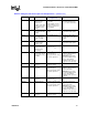
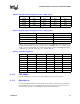
Table 44. Debug Port Pinout Description and Requirements
1
(Sheet 2 of 3)
Name Pin Description
Specification
Requirement
Notes