
Datasheet


Pentium
®
III Xeon™ Processor at 500 and 550 MHz
Datasheet
51
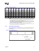
NOTES
1. These values are specified at nominal V
CC
CORE
for the processor core and nominal V
CC
L2
for the L2 cache.
2. Processor power indicates the worst case power that can be dissipated by the entire processor. This value
will be determined after the product has been characterized. It is not possible for the AGTL+ bus, the L2
cache and the processor core to all be at full power simultaneously.
3. The combined power that dissipates through the thermal plate is the thermal plate power. This value will be
determined after the product has been characterized. The value shown follows the expectation that virtually
all of the power will dissipate through the thermal plate.
4. AGTL+ power is the worst case power dissipated in the termination resistors for the AGTL+ bus.
5. “FMB” is a suggested design guideline for a flexible baseboard design. Notice that worst case L2 power and
worst case processor power do not occur on the same processor.
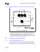
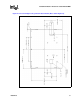
5.1.2 Plate Flatness Specification
The thermal plate flatness for the Pentium
III
Xeon processor is specified to 0.010" across the entire
thermal plate surface, with no more than a 0.003" step anywhere on the surface of the plate, as
shown in Figure 19.
Table 38. Thermal Design Power
1
Processor
Core
Frequency
(MHz)
L2
Cache
Size
Core
Power
(W)
L2
Power
(W)
AGTL+
Power
4
(W)
Processor
Power
2
(W)
Thermal
Plate
Power
3
(W)
Min
T
PLATE
(°C)
Max
T
PLATE
(°C)
Min
T
COVER
(°C)
Max
T
COVER
(°C)
FMB
5
- 35.2 21.0 2 50.0 50.0 0 68 0 75
500 512K 28.0 12.0 2 36.0 37.0 0 75 0 75
500 1M 28.0 19.0 2 44.0 45.0 0 75 0 75
500 2M 28.0 11.6 2 36.2 37.1 0 75 0 75
550 512K 30.8 7.0 2 34.0 35.0 0 68 0 75
550 1M 30.8 7.0 2 34.0 35.0 0 68 0 75
550 2M 30.8 12.4 2 39.5 40.5 0 68 0 75
Figure 19. Plate Flatness Reference
.003/1.00x1.00