
Datasheet

Pentium
®
III Xeon™ Processor at 500 and 550 MHz
Datasheet
35
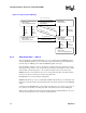
3.3 Non-AGTL+ Signal Quality Specifications
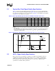
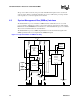
There are three signal quality parameters defined for non-AGTL+ signals: overshoot/undershoot,
ringback, and settling limit. All three signal quality parameters are shown in Figure 15 for the non-
AGTL+ signal group at the processor core pads.
3.3.1 2.5 V Tolerant Buffer Overshoot/Undershoot Guidelines
The overshoot/undershoot guideline limits transitions beyond V
CC
or V
SS
due to fast signal edge
rates. (See Figure 15 for non-AGTL+ signals.) The processor can be damaged by repeated
overshoot or undershoot events on 2. 5V tolerant buffers if great enough. The overshoot/undershoot
guideline is shown in Table 21
.
3.3.2 2.5 V Tolerant Buffer Ringback Specification
The ringback specification is
the voltage at a receiving pin that a signal rings back to after
achieving its maximum absolute value
. (See Figure 15 for an illustration of ringback.) Excessive
ringback can cause false signal detection or extend the propagation delay. Violations of the signal
ringback specification are not allowed for 2 .5V tolerant signals.
Table 22 shows signal ringback specifications for the 2 .5V tolerant signals to be used for
simulations at the processor core.
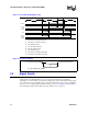
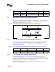
Table 20. AGTL+ Overshoot/Undershoot Guidelines at the Processor Core
Guideline Transition Signal Must Maintain Unit Figure
Overshoot 0
→
1 < 2.7 V 15
Undershoot 1
→
0> -0.7 V15
Figure 15. Non-AGTL+ Overshoot/Undershoot, Settling Limit, and Ringback
Undershoot
Overshoot
Settling Limit
Settling Limit
Rising-Edge
Ringback
Falling-Edge
Ringback
V
LO
V
SS
Time
V =
HI
V
CC
2.5
Voltage
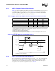
Table 21. 2.5 V Tolerant Signal Overshoot/Undershoot Guidelines at the Processor Core
Guideline Transition Signal Must Maintain Unit Figure
Overshoot 0
→
1 < 3.2 V 15
Undershoot 1
→
0> -0.3 V15