
Datasheet

Pentium
®
III Xeon™ Processor at 500 and 550 MHz
34
Datasheet
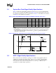
3.2.1 AGTL+ Ringback Tolerance Specifications
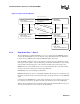
Table 19 provides the AGTL+ signal quality specifications for Pentium
III
Xeon processors for use
in simulating signal quality at the processor core pads. Figure 14 describes the signal quality
waveform for AGTL+ signals at the processor core pads. For more information on the AGTL+
interface, see the
Pentiu
®
II Processor Developer’s Manual
.
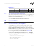
NOTES:
1. Unless otherwise noted, all specifications in this table apply to all Pentium
®
III Xeon™ processor frequencies
and cache sizes.
2. Specifications are for the edge rate of 0.3 - 0.8 V/ns.
3. All values specified by design characterization.
4. Ringback below 2/3 V
TT
+ 20 mV is not supported.
5. Intel recommends performing simulations using a r (rho) of -100 mV to allow margin for other sources of
system noise.
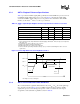
3.2.2 AGTL+ Overshoot/Undershoot Guidelines
The overshoot/undershoot guideline limits transitions beyond V
CC
or V
SS
due to fast signal edge
rates. (Overshoot shown in Figure 15 for non-AGTL+ signals can also be applied to AGTL+
signals.) The processor can be damaged by repeated overshoot or undershoot events if great
enough. The overshoot/undershoot guideline is shown in Table 20
.
Table 19. AGTL+ Signal Groups Ringback Tolerance Specifications at the Processor Core
1, 2, 3
T# Parameter Min Unit Figure Notes
α
: Overshoot 100 mV 14
τ
: Minimum Time at High 0.50 ns 14
ρ
: Amplitude of Ringback –20 mV 14 4, 5
φ
: Final Settling Voltage 20 mV 14
δ
: Duration of Squarewave Ringback N/A ns 14
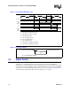
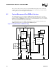
Figure 14. Low to High AGTL+ Receiver Ringback Tolerance
τ
α
ρ
φ
V
start
2/3V
TT
-0.2
Time
Clock
Note: High to Low case is analogous.
δ
1.25V Clk Ref
2/3V
TT
2/3V
TT
+0.2