
Datasheet

Pentium
®
III Xeon™ Processor at 500 and 550 MHz
Datasheet
23
negative current flow due to the active pull-up to V
CC
CORE
in the Pentium III Xeon processor will not be seen
at the processor fingers.
9. The current specified is also for AutoHALT state.
10.Maximum values are specified by design/characterization at nominal V
CC
and at the SC330 connector pins.
11.Based on simulation and averaged over the duration of any change in current. Use to compute the maximum
inductance tolerable and reaction time of the voltage regulator. This parameter is not tested.
NOTES
1. Processor core parameter correlated into a 25
Ω
resistor to a V
TT
of 1.5 V.
2. Excursions above V
TT
to V
CC
CORE
are allowed.
3. (0
≤
V
IN
≤
V
CC
CORE
+ 5%).
4. (0
≤
V
OUT
≤
V
CC
CORE
+ 5%).
5. The processor core drives high for only one clock cycle. It then drives low or tri-states its outputs. V
TT
is
specified in Table 5.
6. Not 100% tested. Specified by design characterization.
7. This R
ON
specification corresponds to a
OL_MAX
of 0.49 V when taken into an effective 25 ohm load to V
TT
of 1.5 V.
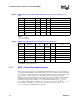
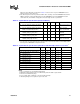
Table 7. AGTL+ Signal Groups, DC Specifications at the Processor Core
Symbol Parameter Min Max Unit Notes
V
IL
Input Low Voltage -0.3 2/3 V
TT
-0.1 V V 5
V
IH
Input High Voltage 2/3 V
TT
+0.1 V V
CC
CORE
V 1, 2, 5
R
ON
N
nMOS On Resistance 12.5 W 6, 7
R
ON
P
pMOS On Resistance 85 W 6
V
OH
TS
Output High Voltage Tri-state V
TT
V1, 5
I
L
Leakage Current ±100 µA 3
I
LO
Output Leakage Current ±15 µA 4
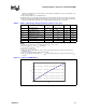
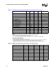
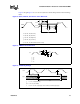
Figure 3. I-V Curve for nMOS Device
0
0.02
0.04
0.06
0.08
0.1
0.12
0 0.1 0.2 0.3 0.4 0.5 0.6 0.7 0.8 0.9 1 1.1 1.2 1.3 1.4 1.5
Vout (V)
IOL (A)