
Datasheet

Pentium
®
III Xeon™ Processor at 500 and 550 MHz
22
Datasheet
connector is specified to have a pin self-inductance of 6.0 nH maximum, a pin-to-pin capacitance of 2 pF
(maximum at 1 MHz), and an average contact resistance over the 6 V
TT
pins of 15 m
Ω
maximum.
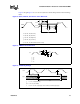
7. These are the tolerance requirements, ac ross a 20MHz bandwidth,
at the processor edge fingers.
The
requirements at the processor edge fingers account for voltage drops (and impedance discontinuities) at the
processor edge fingers and to the processor core. Voltage must return to within the static voltage
specification within 100 us after the transient event. The SC330 connector is specified to have a pin self-
inductance of 6.0 nH maximum, a pin-to-pin capacitance of 2 pF (maximum at 1 MHz), and an average
contact resistance of 15 m
Ω
maximum in order to function with the Intel specified voltage regulator module
(VRM 8.2 or VRM 8.3). Contact Intel for testing details of these parameters. Not 100% tested. Specified by
design characterization.
1
NOTES:
1. Unless otherwise noted, all specifications in this table apply to all processor frequencies and cache sizes.
“FMB” is a suggested design guideline for flexible baseboard design.
2. I
CC
CORE
supplies the processor core.
3. Use the Typical Voltage specification with the Tolerance specifications to provide correct voltage regulation to
the processor.
4. V
TT
must be held t o 1.5V ±9%. It is recommended that V
TT
be held t o 1.5V ±3% while the Pentium
®
III
Xeon™ processor system bus is idle. This is measured at the processor edge fingers.
5. The typical I
CC
CORE
measurements are an average current draw during the execution of Winstone* 96 under
the Windows* 95 operating system. These numbers are meant as a guideline only, not a guaranteed
specification. Actual measurements will vary based upon system environmental conditions and configuration.
6. Max I
CC
measurements are measured at V
CC
nominal voltage under maximum signal loading conditions.
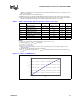
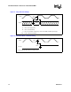
7. Voltage regulators may be designed with a minimum equivalent internal resistance to ensure that the output
voltage, at maximum current output, is no greater than the nominal (i.e., typical) voltage level of V
CC
CORE
(V
CC
CORE_TYP
). In this case, the maximum current level for the regulator, I
CC
COR_REG
, can be reduced from
the specified maximum current I
CC
CORE_MAX
and is calculated by the equation:
I
CC
CORE_REG
= I
CC
CORE_MAX
×
V
CC
CORE_TYP
/ (V
CC
CORE_TYP
+ V
CC
CORE
static tolerance)
8. This is the current required for a single Pentium III Xeon processor. A similar current is drawn through the
termination resistors of each load on the AGTL+ bus. V
TT
is decoupled on the S.E.C. cartridge such that
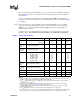
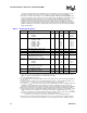
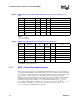
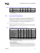
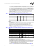
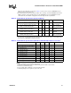
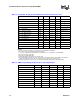
Table 6. Current Specifications
1
Symbol Parameter Min Typ Max Unit Notes
I
CC
CORE
I
CC
for processor core
FMB
1
50 0MHz
55 0MHz
16.0
14.0
15.4
A 2, 5, 6, 7
2, 5, 6, 7
2, 5, 6, 7
I
CC
L2
I
CC
for second level cache
FMB
1
50 0MHz, 5 12KB
50 0MHz, 1MB
50 0MHz, 2MB
55 0MHz ,5 12KB
55 0MHz , 1MB
55 0MHz , 2MB
9.4
3.4
6.8
6.0
3.5
3.5
6.3
A 3, 6, 7
3, 6, 7
3, 6, 7
3, 6, 7
3, 6, 7
3, 6, 7
3, 6, 7
I
VTT
Termination voltage supply current 0 0.3 1.2 A 8
I
SGnt
I
CC
Stop Grant for processor core 0.8 A 6, 9
I
CC
SLP
I
CC
Sleep for processor core 0 0.2 A 6
dlcc
CORE
/dt Core I
CC
slew rate
(at the SC330 connector pins
20 A/µs 10, 11
dlcc
L2
/dt Second level cache I
CC
slew rate
(at the SC330 connector pins
50 0MHz
55 0MHz
10
10
A/
µ
s
10, 11
10, 11
dl
CC
VTT
/dt Termination current slew rate
(at the SC330 connector pins
5A/µs 4, 11
I
CC
TA P
I
CC
for TAP power supply 100 mA
I
CC
SMB
US
I
CC
for SMBus power supply 3 10 mA