
Intel Pentium M Processor with 2-MB L2 Cache and 533-MHz Front Side Bus Datasheet

Datasheet 23
Electrical Specifications
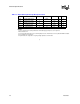
NOTES:
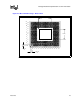
1. These are VID values. Individual processor VID values may be calibrated during manufacturing such that two
devices at the same speed may have different VID settings. Actual voltage supplied to the processor should
be as specified in the load lines in Figures 2 & 3. Adherence to load line specifications is required to ensure
reliable processor operation.
2. The voltage specifications are assumed to be measured at a via on the motherboard’s opposite side of the
processor’s socket (or BGA) ball with a 100-MHz bandwidth oscilloscope, 1.5-pF maximum probe
capacitance, and 1-Mohm minimum impedance. The maximum length of ground wire on the probe should be
less than 5 mm. Ensure external noise from the system is not coupled in the scope probe.
3. Specified at 100C Tj.
4. Specified at the VID voltage.
5. The I
CCDES
(max) specification comprehends future processor HFM frequencies. Platforms should be
designed to this specification.
6. Based on simulations and averaged over the duration of any change in current. Specified by design/
characterization at nominal V
CC
. Not 100% tested.
7. Measured at the bulk capacitors on the motherboard.
8. The Pentium M Processor will support Deeper Sleep voltages of 0.726V(typical) and 0.748V(typical) with the
tolerances specified. A typical voltage setting between 0.726V and 0.748V may also be used but the
minimum/maximum static and ripple tolerances must be within the range specified in the table.
9.
Intel processor numbers are not a measure of performance. Processor numbers differentiate features within
each processor family, not across different processor families. See www.intel.com/products/
processor_number for details.
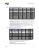
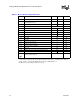
I
DPRSLP1
I
CC
Deeper Sleep @0.748 V 3.9 A 4,9
I
DPRSLP2
I
CC
Deeper Sleep @0.726 V 3.7 A 4,9
dI
CC/DT
V
CC
power supply current slew rate 0.5 A/ns 6, 8
I
CCA
I
CC
for V
CCA
supply 120 mA
I
CCP
I
CC
for V
CCP
supply 2.5 A
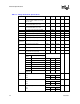
Table 3-5. Voltage and Current Specifications
Symbol Parameter Min Typ Max Unit Notes
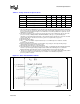
Figure 3-1. Active VCC and ICC Load Line