
Intel Pentium M Processor with 2-MB L2 Cache and 533-MHz Front Side Bus Datasheet


62 Datasheet
Thermal Specifications and Design Considerations
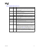
NOTES:
1. Intel does not support or recommend operation of the thermal diode under reverse bias. Intel does not
support or recommend operation of the thermal diode when the processor power supplies are not within their
specified tolerance range.
2. Characterized at 100 °C.
3. Not 100% tested. Specified by design/characterization.
4. The ideality factor, n, represents the deviation from ideal diode behavior as exemplified by the diode
equation:
I
FW
=I
s
*(e
(qVD/nkT)
-1)
Where I
S
= saturation current, q = electronic charge, V
D
= voltage across the diode, k = Boltzmann Constant,
and T = absolute temperature (Kelvin).
Value shown in the table is not the Pentium M Processor thermal diode ideality factor. It is a reference value
used to calculate
Pentium M thermal diode temperature offset.
5. The series resistance, R
T
, is provided to allow for a more accurate measurement of the diode junction
temperature. R
T
as defined includes the pins of the processor but does not include any socket resistance or
board trace resistance between the socket and the external remote diode thermal sensor. R
T
can be used by
remote diode thermal sensors with automatic series resistance cancellation to calibrate out this error term.
Another application is that a temperature offset can be manually calculated and programmed into an offset
register in the remote diode thermal sensors as exemplified by the equation:
T
error
= [R
T
*(N-1)*I
FWmin
]/[(no/q)*ln N]
6. Offset value is programmed in processor Model Specific Register.
5.1.3 Intel
®
Thermal Monitor
The Intel
®
Thermal Monitor helps control the processor temperature by activating the TCC when
the processor silicon reaches its maximum operating temperature. The temperature at which Intel
Thermal Monitor activates the thermal control circuit is not user configurable and is not software
visible. Bus traffic is snooped in the normal manner, and interrupt requests are latched (and
serviced during the time that the clocks are on) while the TCC is active.
With a properly designed and characterized thermal solution, it is anticipated that the TCC would
only be activated for very short periods of time when running the most power intensive
applications. The processor performance impact due to these brief periods of TCC activation is
expected to be so minor that it would not be detectable. An under-designed thermal solution that is
not able to prevent excessive activation of the TCC in the anticipated ambient environment may
cause a noticeable performance loss, and may affect the long-term reliability of the processor. In
addition, a thermal solution that is significantly under designed may not be capable of cooling the
processor even when the TCC is active continuously.
The Intel Thermal Monitor controls the processor temperature by modulating (starting and
stopping) the processor core clocks or by initiating an Enhanced Intel SpeedStep Technology
transition when the processor silicon reaches its maximum operating temperature. The Intel
Thermal Monitor uses two modes to activate the TCC: Automatic mode and on-demand mode. If
both modes are activated, Automatic mode takes precedence.
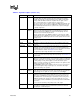
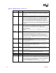
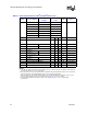
Table 5-3. Thermal Diode Specifications
Symbol Parameter Min Typ Max Unit Notes
I
FW
Forward Bias Current 5 300 A Note 1
Toffset Thermal diode temperature
offset
-4 11 °C 2, 6
n Reference Diode Ideality
Factor used to calculate
temperature offset
1.0022 Notes 2, 3,
4
R
T
Series Resistance 3.06 ohms 2, 3, 5