Intel® Pentium® M Processor with 2-MB L2 Cache and 533-MHz Front Side Bus Datasheet July 2005 Reference Number: 305262-002
INFORMATION IN THIS DOCUMENT IS PROVIDED IN CONNECTION WITH INTEL PRODUCTS. NO LICENSE, EXPRESS OR IMPLIED, BY ESTOPPEL OR OTHERWISE, TO ANY INTELLECTUAL PROPERTY RIGHTS IS GRANTED BY THIS DOCUMENT.
Contents 1 1.1 1.2 2 2.1 2.2 2.3 2.4 3 3.1 3.2 3.3 3.4 3.5 3.6 3.7 3.8 3.9 3.10 4 4.1 4.2 5 5.1 Introduction.................................................................................................................................... 7 Terminology .................................................................................................................................. 8 References ...............................................................................................................
Figures 2-1 3-1 3-2 4-1 4-2 4-3 4-4 4-5 4-6 4-7 Clock Control States................................................................................................................11 Active VCC and ICC Load Line ...............................................................................................23 Deep Sleep VCC and ICC Load Line ......................................................................................24 Micro-FCPGA Package Top and Bottom Isometric Views ............................
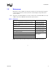
Revision History Revision 001 002 Description Initial release ® Date January 2005 ® Added Intel Pentium M Processor 780 specifications July 2005 § Datasheet 5
Datasheet
Introduction 1 Introduction The Intel® Pentium® M Processor with 533-MHz front side bus (FSB) is the next generation highperformance, low-power mobile processor based on the Pentium M Processor architecture. All instances of the Pentium M Processor in this document refer to the Pentium M Processor with 2-MB L2 cache and 533-MHz front side bus unless stated otherwise. This document contains specifications for the Pentium M Processor 780, 770, 760, 750, 740, 730∆.
Introduction address bus provide a data bus bandwidth of up to 4.3 GB/second. The FSB uses Advanced Gunning Transceiver Logic (AGTL+) signaling technology, a variant of GTL+ signaling technology with low power enhancements. The processor features Enhanced Intel SpeedStep Technology, which enables real-time dynamic switching between multiple voltage and frequency points. This results in optimal performance without compromising low power.
Introduction 1.2 References Material and concepts available in the following documents may be beneficial when reading this document. Chipset references in this document are to Intel 915 Express chipset family unless specified otherwise. Note: All instances of the Pentium M Processor in this document refer to the Pentium M Processor with 2-MB L2 cache and 533-MHz Front Side Bus unless stated otherwise. . Table 1-1.
Introduction 10 Datasheet
Low Power Features 2 Low Power Features 2.1 Clock Control and Low Power States The Pentium M Processor supports the AutoHALT, Stop Grant, Sleep, Deep Sleep, and Deeper Sleep states for optimal power management. See Figure 2-1 for a visual representation of the processor low-power states. 2.1.1 Normal State This is the normal operating state for the processor. 2.1.2 AutoHALT Powerdown State AutoHALT is a low-power state entered when the processor executes the HALT instruction.
Low Power Features 2.1.3 Stop-Grant State When the STPCLK# pin is asserted, the Stop-Grant state of the processor is entered 20 bus clocks after the response phase of the processor-issued Stop Grant Acknowledge special bus cycle. Since the AGTL+ signal pins receive power from the FSB, these pins should not be driven (allowing the level to return to VCCP) for minimum power drawn by the termination resistors in this state. In addition, all other input pins on the FSB should be driven to the inactive state.
Low Power Features In the Sleep state, the processor is incapable of responding to snoop transactions or latching interrupt signals. No transitions or assertions of signals (with the exception of SLP#, DPSLP# or RESET#) are allowed on the FSB while the processor is in Sleep state. Any transition on an input signal before the processor has returned to Stop-Grant state will result in unpredictable behavior.
Low Power Features 2.2 Enhanced Intel SpeedStep® Technology The Pentium M Processor features Enhanced Intel SpeedStep Technology. Unlike previous implementations of Intel SpeedStep Technology, this technology enables the processor to switch between multiple frequency and voltage points instead of two. This will enable superior performance with optimal power savings. Switching between states is software controlled unlike previous implementations where the GHI# pin is used to toggle between two states.
Low Power Features 2.3 FSB Low Power Enhancements The Pentium M Processor incorporates the following FSB low power enhancements: • • • • Dynamic FSB Power Down BPRI# control for address and control input buffers Dynamic On Die Termination disabling Low VCCP (I/O termination voltage) The Pentium M Processor incorporates the DPWR# signal that controls the data bus input buffers on the processor.
Low Power Features 16 Datasheet
Electrical Specifications 3 Electrical Specifications 3.1 Power and Ground Pins For clean, on-chip power distribution, the Pentium M Processor will have a large number of VCC (power) and VSS (ground) inputs. All power pins must be connected to VCC power planes while all VSS pins must be connected to system ground planes. Use of multiple power and ground planes is recommended to reduce I*R drop. The processor VCC pins must be supplied the voltage determined by the VID (Voltage ID) pins. 3.
Electrical Specifications Table 3-1. Voltage Identification Definition VID 3.4 5 4 3 2 1 0 0 0 0 0 0 0 0 0 0 0 0 1 0 0 0 0 1 0 0 0 0 0 0 0 0 0 0 VCC V VID VCC V 5 4 3 2 1 0 1.708 1 0 0 0 0 0 1.196 1.692 1 0 0 0 0 1 1.180 0 1.676 1 0 0 0 1 0 1.164 1 1 1.660 1 0 0 0 1 1 1.148 1 0 0 1.644 1 0 0 1 0 0 1.132 0 1 0 1 1.628 1 0 0 1 0 1 1.116 0 0 1 1 0 1.612 1 0 0 1 1 0 1.100 0 0 0 1 1 1 1.
Electrical Specifications 3.5 Signal Terminations and Unused Pins All RSVD (RESERVED) pins must remain unconnected. Connection of these pins to VCC, VSS, or to any other signal (including each other) can result in component malfunction or incompatibility with future Pentium M Processors. See Section 4.1 for a pin listing of the processor and the location of all RSVD pins. For reliable operation, always connect unused inputs or bidirectional signals to an appropriate signal level.
Electrical Specifications Table 3-3. FSB Pin Groups Signal Group Signals1 Type AGTL+ Common Clock Input Synchronous to BCLK[1:0] BPRI#, DEFER#, DPWR#, PREQ#, RESET#, RS[2:0]#, TRDY# AGTL+ Common Clock I/O Synchronous to BCLK[1:0] ADS#, BNR#, BPM[3:0]#3, BR0#, DBSY#, DRDY#, HIT#, HITM#, LOCK#, PRDY#3 AGTL+ Source Synchronous I/O Synchronous to assoc.
Electrical Specifications 3.9 Maximum Ratings Table 3-4 lists the processor’s maximum environmental stress ratings. The processor should not receive a clock while subjected to these conditions. Functional operating parameters are listed in the AC and DC tables. Extended exposure to the maximum ratings may affect device reliability.
Electrical Specifications Table 3-5. Voltage and Current Specifications Symbol Parameter Min VCCHFM1 Vcc at Highest Frequency Mode (HFM) for Intel® Pentium® M Processors 730, 740, 750, 760 VCCHFM2 Typ Max Unit 1.260 1.356 V 1, 2 Vcc at Highest Frequency Mode (HFM) for the Pentium M Processor 770 1.260 1.372 V 1, 2 VCCHFM3 Vcc at Highest Frequency Mode (HFM) for the Pentium M Processor 780 1.260 1.
Electrical Specifications Table 3-5. Voltage and Current Specifications Symbol Parameter Min Typ Max Unit Notes IDPRSLP1 ICC Deeper Sleep @0.748 V 3.9 A 4,9 IDPRSLP2 ICC Deeper Sleep @0.726 V 3.7 A 4,9 dICC/DT VCC power supply current slew rate 0.5 A/ns 6, 8 ICCA ICC for VCCA supply 120 mA ICCP ICC for VCCP supply 2.5 A NOTES: 1. These are VID values.
Electrical Specifications Figure 3-2. Deep Sleep VCC and ICC Load Line V CC [V ] S lope= -3.0 m V /A 10m V = R IP P LE Vcc nom {H FM |LFM } - 1.2% +/-1.5% from N om inal =VR Error I 0 CC [A ] I C C m ax D eep S leep {H FM |LFM } Table 3-6. FSB Differential BCLK Specifications Min Typ Max Parameter VL Input Low Voltage VH Input High Voltage 0.660 0.710 0.85 V VCROSS Crossing Voltage 0.25 0.35 0.55 V 2 ∆VCROSS Range of Crossing Points N/A N/A 0.
Electrical Specifications Table 3-7. AGTL+ Signal Group DC Specifications Symbol Parameter Min Typ Max Unit Notes1 VCCP I/O Voltage 0.997 1.05 1.102 V GTLREF Reference Voltage 2/3 VCCP 2% 2/3 VCCP 2/3 VCCP + 2% V 6 VIH Input High Voltage GTLREF+0.1 VCCP+0.1 V 3,6 VIL Input Low Voltage -0.1 GTLREF-0.
Electrical Specifications . Table 3-9. Open Drain Signal Group DC Specifications Min Typ Max Unit Notes1 V 3 Symbol Parameter VOH Output High Voltage VOL Output Low Voltage 0 0.20 V IOL Output Low Current 16 50 mA 2 ILO Leakage Current ± 200 µA 4 Cpad Pad Capacitance 3.0 pF 5 VCCP 1.7 2.3 NOTES: 1. Unless otherwise noted, all specifications in this table apply to all processor frequencies. 2. Measured at 0.2 V 3.
Package Mechanical Specifications and Pin Information 4 Package Mechanical Specifications and Pin Information The Pentium M Processor will be available in 478 pin Micro-FCPGA and 479 ball Micro-FCBGA packages. The Pentium M Processors 780, 770, 760, 750, 740 and 730 will also be available in a lead free SLI (second level interconnect) version of the Micro-FCBGA package. Package specifications are the same for all Micro-FCBGA packages.
Package Mechanical Specifications and Pin Information Figure 4-2. Micro-FCPGA Package - Top and Side Views SUBSTRATE KEEPO UT ZO NE DO NO T CONTACT PACKAG E IN S ID E T H IS L IN E 7 (K 1) 8 p la ce s 5 (K) 4 p la ce s 0 .2 8 6 A 1 .2 5 M A X (A 3) D1 3 5 (D ) Ø 0 .3 2 (B ) 4 7 8 p la ce s E1 3 5 (E) A2 P IN A 1 C O R N ER 2 .0 3 ± 0 .0 8 (A 1) NOTE: Die is centered. All dimensions in millimeters. Values shown for reference only. Refer to Table 4-1 for details.
Package Mechanical Specifications and Pin Information Figure 4-3. Micro-FCPGA Package - Bottom View 14 (K3) AF AD AB Y V T P M K H F D B AE AC AA W U R 14 (K3 ) N L J G E C A 1 25X 1.27 (e) 3 2 5 4 7 6 9 8 13 11 10 12 15 14 17 16 19 18 21 20 23 22 25 24 26 2 5X 1.27 (e) NOTE: All dimensions in millimeters. Values shown for reference only. Refer to Table 4-1 for details.
Package Mechanical Specifications and Pin Information Table 4-1. Micro-FCPGA Package Dimensions Symbol Parameter Min Max Unit A Overall height, top of die to package seating plane 1.88 2.02 mm – Overall height, top of die to PCB surface, including socket (Refer to Note 1) 4.74 5.16 mm A1 Pin length 1.95 2.11 mm A2 Die height A3 Pin-side capacitor height – 1.25 mm B Pin diameter 0.28 0.36 mm D Package substrate length 34.9 35.1 mm Package substrate width 34.9 E 0.
Package Mechanical Specifications and Pin Information Figure 4-4.
Package Mechanical Specifications and Pin Information Figure 4-5. Micro-FCBGA Package Top and Side Views SUBSTRATE KEEPOUT ZONE DO NOT CONTACT PACKAGE INSIDE THIS LINE 7 (K1) 8 places 5 (K) 4 places 0.20 A A2 D1 35 (D) Ø 0.78 (b) 479 places E1 35 (E) K2 PIN A1 CORNER NOTE: Die is centered. All dimensions in millimeters. Values shown for reference only. Refer to Table 4-2 for details.
Package Mechanical Specifications and Pin Information Table 4-2. Micro-FCBGA Package Dimensions Symbol Parameter Min Max 2.60 2.85 Unit A Overall height, as delivered (Refer to Note 1) A2 Die height 0.82 mm b Ball diameter 0.78 mm D Package substrate length 34.9 35.1 mm E Package substrate width 34.9 35.1 mm D1 Die length 12.54 mm E1 Die width 6.99 mm e Ball pitch 1.
Package Mechanical Specifications and Pin Information Figure 4-6. Micro-FCBGA Package Bottom View 1.625 (S) 4 places AF AD AB Y V T P M K H F D B AE AC 1.625 (S) 4 places AA W U R N L J G E C A 1 25X 1.27 (e) 3 2 5 4 7 6 9 8 13 11 10 12 15 14 17 16 19 18 21 20 23 22 25 24 26 25X 1.27 (e) NOTE: All dimensions in millimeters. Values shown for reference only. Refer to Table 4-2 for details.
Package Mechanical Specifications and Pin Information 4.1 Processor Pinout and Pin List Figure 4-7 on the next page shows the top view pinout of Pentium M Processor. The pin list arranged in two different formats is shown in the following pages. Figure 4-7.
Package Mechanical Specifications and Pin Information This page is intentionally left blank.
Table 4-3. Pin Listing by Pin Name Table 4-3.
Table 4-3. Pin Listing by Pin Name Pin Name Pin Number Signal Buffer Type Direction Table 4-3.
Table 4-3. Pin Listing by Pin Name Pin Name Pin Number Signal Buffer Type Direction Table 4-3.
Table 4-3. Pin Listing by Pin Name Pin Name Pin Number Signal Buffer Type Direction Table 4-3.
Table 4-3. Pin Listing by Pin Name Pin Name Pin Number Signal Buffer Type Direction Table 4-3.
Table 4-3. Pin Listing by Pin Name Pin Name Pin Number Signal Buffer Type Direction Table 4-3.
Table 4-3. Pin Listing by Pin Name Pin Number Pin Name Signal Buffer Type Table 4-4.
Table 4-4. Pin Listing by Pin Number Pin Number Pin Name Signal Buffer Type AA25 VSS Power/Other AA26 D[46]# Source Synch AB1 COMP[3] AB2 AB3 Direction Table 4-4.
Table 4-4. Pin Listing by Pin Number Pin Number Pin Name Signal Buffer Type Direction Table 4-4.
Table 4-4. Pin Listing by Pin Number Pin Number Pin Name Signal Buffer Type B21 D[3]# Source Synch B22 VSS Power/Other B23 D[13]# Source Synch B24 D[9]# Source Synch B25 VSS Power/Other B26 D[5]# Source Synch C1 VSS Power/Other Direction Input/Output Table 4-4.
Table 4-4. Pin Listing by Pin Number Pin Number Pin Name Signal Buffer Type Direction Table 4-4.
Table 4-4. Pin Listing by Pin Number Pin Number Pin Name Signal Buffer Type Direction Table 4-4.
Table 4-4.
Contents This page is intentionally left blank.
4.2 Alphabetical Signals Reference Table 4-5. Signal Description (Sheet 1 of 7) Name Type Description A[31:3]# Input/ Output A[31:3]# (Address) define a 232-byte physical memory address space. In subphase 1 of the address phase, these pins transmit the address of a transaction. In sub-phase 2, these pins transmit transaction type information. These signals must connect the appropriate pins of both agents on Intel® Pentium® M Processor FSB.
Table 4-5. Signal Description (Sheet 2 of 7) Name Type Description BSEL[1:0] Output BSEL[1:0] (Bus Select) are used to select the processor input clock frequency. Table 3-2 defines the possible combinations of the signals and the frequency associated with each combination. The required frequency is determined by the processor, chipset and clock synthesizer. All agents must operate at the same frequency. The Pentium M Processor operates at a 533-MHz front side bus frequency (133 MHz BCLK).
Table 4-5. Signal Description (Sheet 3 of 7) Name DINV[3:0]# Type Description Input/ Output DINV[3:0]# (Data Bus Inversion) are source synchronous and indicate the polarity of the D[63:0]# signals. The DINV[3:0]# signals are activated when the data on the data bus is inverted. The bus agent will invert the data bus signals if more than half the bits, within the covered group, would change level in the next cycle.
Table 4-5. Signal Description (Sheet 4 of 7) Name Type Description FERR#/PBE# Output FERR# (Floating-point Error)PBE#(Pending Break Event) is a multiplexed signal and its meaning is qualified with STPCLK#. When STPCLK# is not asserted, FERR#/PBE# indicates a floating point when the processor detects an unmasked floating-point error. FERR# is similar to the ERROR# signal on the Intel 387 coprocessor, and is included for compatibility with systems using MSDOS*-type floating-point error reporting.
Table 4-5. Signal Description (Sheet 5 of 7) Name LINT[1:0] Type Input Description LINT[1:0] (Local APIC Interrupt) must connect the appropriate pins of all APIC Bus agents. When the APIC is disabled, the LINT0 signal becomes INTR, a maskable interrupt request signal, and LINT1 becomes NMI, a nonmaskable interrupt. INTR and NMI are backward compatible with the signals of those names on the Pentium Processor. Both signals are asynchronous.
Table 4-5. Signal Description (Sheet 6 of 7) Name Type Description RSVD Reserved/ No Connect These pins are RESERVED and must be left unconnected on the board. However, it is recommended that routing channels to these pins on the board be kept open for possible future use. Please refer to the platform design guide for more details. SLP# Input SLP# (Sleep), when asserted in Stop-Grant state, causes the processor to enter the Sleep state.
Table 4-5. Signal Description (Sheet 7 of 7) Name TMS Type Input Description TMS (Test Mode Select) is a JTAG specification support signal used by debug tools. Please refer to the platform design guide for termination requirements and implementation details. TRDY# Input TRDY# (Target Ready) is asserted by the target to indicate that it is ready to receive a write or implicit writeback data transfer. TRDY# must connect the appropriate pins of both FSB agents.
Datasheet
Thermal Specifications and Design Considerations 5 Thermal Specifications and Design Considerations The Pentium M Processor requires a thermal solution to maintain temperatures within operating limits as set forth in Section 5.1. Any attempt to operate that processor outside these operating limits may result in permanent damage to the processor and potentially other components in the system. As processor technology changes, thermal management becomes increasingly crucial when building computer systems.
Thermal Specifications and Design Considerations Table 5-1. Power Specifications for Intel® Pentium® M Processor Thermal Design Power Unit Notes 2.26 GHz & HFM Vcc 27 W 770 2.13 GHz & HFM Vcc 27 At 100 °C, Notes 1, 4 760 2.00 GHz & HFM Vcc 27 750 1.86 GHz & HFM Vcc 27 740 1.73 GHz & HFM Vcc 27 730 1.60 GHz & HFM Vcc 27 Not Applicable 800 MHz & LFM Vcc 10.
Thermal Specifications and Design Considerations 5.1 Thermal Specifications 5.1.1 Thermal Diode The Pentium M Processor incorporates two methods of monitoring die temperature, the Intel® Thermal Monitor and the thermal diode. The Intel Thermal Monitor (detailed in Section 5.1) must be used to determine when the maximum specified processor junction temperature has been reached.
Thermal Specifications and Design Considerations Table 5-3. Thermal Diode Specifications Symbol Parameter Min Typ Max Unit Notes IFW Forward Bias Current 5 300 µA Note 1 Toffset Thermal diode temperature offset -4 11 °C 2, 6 n Reference Diode Ideality Factor used to calculate temperature offset RT Series Resistance 1.0022 3.06 Notes 2, 3, 4 ohms 2, 3, 5 NOTES: 1. Intel does not support or recommend operation of the thermal diode under reverse bias.
Thermal Specifications and Design Considerations Note: The Intel Thermal Monitor automatic mode must be enabled through BIOS for the processor to be operating within specifications. There are two automatic modes called Intel Thermal Monitor 1 and Intel Thermal Monitor 2. These modes are selected by writing values to the Model Specific Registers (MSRs) of the processor.
Thermal Specifications and Design Considerations Besides the thermal sensor and thermal control circuit, the Intel Thermal Monitor thermal monitor feature also includes one ACPI register, one performance counter register, three model specific registers (MSR), and one I/O pin (PROCHOT#). All are available to monitor and control the state of the Intel Thermal Monitor feature. The Intel Thermal Monitor can be configured to generate an interrupt upon the assertion or deassertion of PROCHOT#.