
Intel Pentium M Processor Datasheet


Intel
®
Pentium
®
M Processor Datasheet 71
Thermal Specifications and Design Considerations
2. Not 100% tested. These power specifications are determined by characterization of the processor currents at
higher temperatures and extrapolating the values for the temperature indicated.
3. As measured by the on-die Intel Thermal Monitor. The Intel Thermal Monitor’s automatic mode is used to
indicate that the maximum T
J
has been reached. Refer to Section 5.1 for more details.
4. The Intel Thermal Monitor automatic mode must be enabled for the processor to operate within
specifications.
5.1 Thermal Specifications
5.1.1 Thermal Diode
The Intel Pentium M processor incorporates two methods of monitoring die temperature, the Intel
Thermal Monitor and the thermal diode. The Intel Thermal Monitor (detailed in Section 5.1) must
be used to determine when the maximum specified processor junction temperature has been
reached. The second method, the thermal diode, can be read by an off-die analog/digital converter
(a thermal sensor) located on the motherboard, or a stand-alone measurement kit. The thermal
diode may be used to monitor the die temperature of the processor for thermal management or
instrumentation purposes but cannot be used to indicate that the maximum T
J
of the processor has
been reached. Please see Section 5.1.2 for thermal diode usage recommendation when the
PROCHOT# signal is not asserted.
Table 24 and Table 25 provide the diode interface and specifications.
Note: The reading of the external thermal sensor (on the motherboard) connected to the processor
thermal diode signals, will not necessarily reflect the temperature of the hottest location on the die.
This is due to inaccuracies in the external thermal sensor, on-die temperature gradients between the
location of the thermal diode and the hottest location on the die, and time based variations in the die
temperature measurement. Time based variations can occur when the sampling rate of the thermal
diode (by the thermal sensor) is slower than the rate at which the T
J
temperature can change.
The offset between the thermal diode based temperature reading and the Intel Thermal Monitor
reading can be characterized using the Intel Thermal Monitor’s automatic mode activation of the
thermal control circuit. This temperature offset must be taken into account when using the
processor thermal diode to implement power management events.
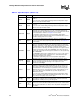
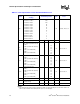
Table 24. Thermal Diode Interface
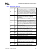
Table 25. Thermal Diode Specifications
NOTES:
Signal Name Pin/Ball Number Signal Description
THERMDA B18 Thermal diode anode
THERMDC A18 Thermal diode cathode
Symbol Parameter Min Typ Max Unit Notes
I
FW
Forward Bias Current 5 300 µA Note 1
n Diode Ideality Factor 1.00151 1.00220 1.00289 Notes 2, 3, 4
R
T
Series Resistance 3.06 ohms 2, 3, 5