
Guide


Thermal and Mechanical Design
Intel® Xeon® Processor E7 2800/4800/8800 v2 Product Family 59
Thermal/ Mechanical Specifications and Design Guide
Designs that do not meet the design objectives of the back plate or exceed the
maximum Heatsink Static Compressive Load, should follow Board Deflection
Measurement Methodology as outlined to assess risk to socket solder joint reliability.
2.5 Reference Thermal Solution
This section describes the Intel reference heatsink design and performance
specifications in accordance with the Intel® Xeon® Processor E7 2800/4800/8800 v2
Product Family thermal and mechanical specifications. System form factor compatibility
and thermal boundary conditions applied in designing the Intel reference heatsink are
provided in Table 2-19.
2.5.1 Processor Heatsink Design Boundary Conditions
Heatsink thermal characteristics vary with change in its thermal environment such as,
airflow rate, air temperature passing through (Tla), and the processor power
dissipation. Only one set of boundary conditions is considered in design the reference
solution. By varying the air flow rate, heatsink performance under various conditions is
achievable.
Notes:
1. Identifies processor power dissipation. Range is based on the processor SKUs. See processor thermal
specification for support SKUs.
2. Local ambient temperature of the air entering the heatsink.
3. Heatsink performance target is based on the processor highest TDP SKU power dissipation, the system
form factor, and environmental conditions.
4. Defined as (T
CASE_MAX
- T
LA
) / TDP
5. Airflow through the heatsink fins with zero bypass. Max target for pressure drop (
ΔP) measured in inches
H
2
O.
6. Reference system configuration. 1U = 1.75”.
7. Dimensions of heatsink do not include socket or processor.
8. Thermal Interface Material is phase change material. See supplier specification for additional information.
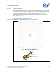
2.5.2 Tower Heatsink Design
Intel reference heatsink design utilizes heatpipe technology with aluminum frame base
with cooper slug and aluminum fins.
Table 2-19. Processor Boundary Conditions and Performance Targets
Parameter Value Notes
Altitude, system ambient temp Sea level, 35
o
C
TDP 105-165W
1
T
LA
47
°
C 2
Ψ
CA
0.197
o
C/W
3, 4
Airflow 33.5 CFM @ 0.23” ΔP 5
System height
(form factor)
4U 6
Heatsink volumetric 95 x 105.5 x 100 mm 7
Thermal Interface Material (TIM) Honeywell* PCM45F 8
Heatsink Mass < 600g