R Intel® 6700PXH 64-bit PCI Hub Thermal/Mechanical Design Guidelines August 2004 Document Number: 302817-003
R INFORMATION IN THIS DOCUMENT IS PROVIDED IN CONNECTION WITH INTEL® PRODUCTS. EXCEPT AS PROVIDED IN INTEL'S TERMS AND CONDITIONS OF SALE FOR SUCH PRODUCTS, INTEL ASSUMES NO LIABILITY WHATSOEVER, AND INTEL DISCLAIMS ANY EXPRESS OR IMPLIED WARRANTY RELATING TO SALE AND/OR USE OF INTEL PRODUCTS, INCLUDING LIABILITY OR WARRANTIES RELATING TO FITNESS FOR A PARTICULAR PURPOSE, MERCHANTABILITY, OR INFRINGEMENT OF ANY PATENT, COPYRIGHT, OR OTHER INTELLECTUAL PROPERTY RIGHT.
R Contents 1 Introduction.....................................................................................................................7 1.1 Definition of Terms ...............................................................................................7 1.2 Reference Documents .........................................................................................8 2 Packaging Technology...................................................................................................9 2.
R Figures 2-1. Intel® 6700PXH 64-bit PCI Hub Package Dimensions (Top View) .............................9 2-2. Intel® 6700PXH 64-bit PCI Hub Package Dimensions (Side View).............................9 2-3. Intel® 6700PXH 64-bit PCI Hub Package Dimensions (Bottom View) ......................10 5-1. Zero Degree Angle Attach Heatsink Modifications ...................................................16 5-2. Zero Degree Angle Attach Methodology (Top View) ................................................16 6-1.
R Revision History Revision Number ® Description Date -001 Initial release Jul 2004 -002 Added “reference thermal solution rails to PXH package” footprint drawing in Section 6.
R Introduction 6 ® Intel 6700PXH 64-bit PCI Hub Thermal/Mechanical Design Guidelines
R 1 Introduction As the complexity of computer systems increases, so do the power dissipation requirements. Care must be taken to ensure that the additional power is properly dissipated. Typical methods to improve heat dissipation include selective use of ducting, and/or passive heatsinks. The goals of this document are to: • Outline the thermal and Mechanical operating limits and specifications for the Intel® 6700PXH 64-bit PCI Hub component.
R Introduction 1.2 Tcase_max Maximum die temperature allowed. This temperature is measured at the geometric center of the top of the package die. Tcase_min Minimum die temperature allowed. This temperature is measured at the geometric center of the top of the package die. TDP Thermal design power. Thermal solutions should be designed to dissipate this target power level. TDP is not the maximum power that the chipset can dissipate.
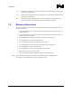
R 2 Packaging Technology The Intel® 6700PXH 64-bit PCI Hub component uses a 31 mm x 31 mm, 8-layer FC-BGA package (see Figure 2-1Figure 2-1Figure 2-1, Figure 2-2Figure 2-2Figure 2-2, and Figure 2-3Figure 2-3Figure 2-3). Figure 2-1. Intel® 6700PXH 64-bit PCI Hub Package Dimensions (Top View) Handling Exclusion Area 0.547 in. Die Keepout Area 0.491 in. 0.291 in. PXH Die 0.247 in. 17.00 mm 21.00 mm 31.00 mm 0.200 in. 17.00 mm 21.00 mm 31.00 mm Figure 2-2.
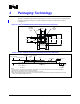
R Packaging TechnologyPackaging TechnologyPackaging Technology Figure 2-3. Intel® 6700PXH 64-bit PCI Hub Package Dimensions (Bottom View) 4X 0.635 4X 15.500 23X 1.270 AD AC AB AA Y W V U T R P N M L K J H G F E D C B A 31.000 + 0.100 + + 1 (0.895) 2 16 18 20 22 24 4 6 8 10 12 14 15 17 19 21 23 3 5 7 9 11 13 23X 1.270 A 8X 14.605 29.2100 31.000 + 0.100 0.200 C A B NOTES: 1. All dimensions are in millimeters. 2. All dimensions and tolerances conform to ANSI Y14.5M-1994. 2.
R 3 Thermal Specifications 3.1 Thermal Design Power (TDP) Analysis indicates that real applications are unlikely to cause the PXH component to consume maximum power dissipation for sustained time periods. Therefore, in order to arrive at a more realistic power level for thermal design purposes, Intel characterizes power consumption based on known platform benchmark applications. The resulting power consumption is referred to as the Thermal Design Power (TDP).
Thermal SpecificationsThermal Simulation 12 ® R Intel 6700PXH 64-bit PCI Hub Thermal/Mechanical Design Guidelines
R 4 Thermal Simulation Intel provides thermal simulation models of the Intel® 6700PXH 64-bit PCI Hub component and associated user's guides to aid system designers in simulating, analyzing, and optimizing their thermal solutions in an integrated, system-level environment. The models are for use with the commercially available Computational Fluid Dynamics (CFD)-based thermal analysis tool “FLOTHERM”* (version 3.1 or higher) by Flomerics, Inc. These models are also available in IcePak* format.
R Thermal SimulationThermal Simulation 14 ® Intel 6700PXH 64-bit PCI Hub Thermal/Mechanical Design Guidelines
R 5 Thermal Metrology The system designer must make temperature measurements to accurately determine the thermal performance of the system. Intel has established guidelines for proper techniques to measure the PXH die temperatures. Section 5.1 provides guidelines on how to accurately measure the PXH die temperatures. 5.
R Thermal MetrologyThermal MetrologyThermal Metrology Figure 5-1. Zero Degree Angle Attach Heatsink Modifications NOTE: Not to scale. Figure 5-2. Zero Degree Angle Attach Methodology (Top View) Die Thermocouple Wire Cement + Thermocouple Bead Substrate 001321 NOTE: Not to scale.
R 6 Reference Thermal Solution Intel has developed one reference thermal solution to meet the cooling needs of the PXH component under operating environments and specifications defined in this document. This chapter describes the overall requirements for the reference thermal solution including critical-to-function dimensions, operating environment, and validation criteria.
R Reference Thermal SolutionReference Thermal SolutionReference Thermal Solution 6.3 Mechanical Design Envelope While each design may have unique mechanical volume and height restrictions or implementation requirements, the height, width, and depth constraints typically placed on the PXH thermal solution are shown in Figure 6-2Figure 6-2Figure 6-2.
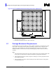
R Reference Thermal SolutionReference Thermal SolutionReference Thermal Solution Figure 6-3. Torsional Clip Heatsink Board Component Keepout Component keepout area 1.756 PXH 1.886 2x 0.943 Parallel Mean Airflow Direction Max component Height 0.50 2x 0.878 NOTE: All dimensions are in inches. Figure 6-4. Retention Mechanism Component Keepout Zones Component Keepout Area 0.500 2x 0.060 0.120 0.345 0.225 0.050" Component Keepout 0.170 0.750 (0.165) Detail A (0.345) See Detail A 0.100 0.165 0.
Reference Thermal SolutionReference Thermal SolutionReference Thermal Solution 6.5.1 R Heatsink Orientation Since this solution is based on a unidirectional heatsink, mean airflow direction must be aligned with the direction of the heatsink fins. Figure 6-5. Torsional Clip Heatsink Assembly Figure 6-6 Heatsink Rails to PXH Package Footprint 6.5.2 Extruded Heatsink Profiles The reference torsional clip heatsink uses an extruded heatsink for cooling the PXH component.
R 6.5.4 Reference Thermal SolutionReference Thermal SolutionReference Thermal Solution Thermal Interface Material A thermal interface material provides improved conductivity between the die and heatsink. The reference thermal solution uses Chomerics* T-710, 0.127 mm (0.005 in.) thick, 8 mm x 8 mm square. Note: Unflowed or “dry” Chomerics* T710 has a material thickness of 0.005 inch. The flowed or “wet” Chromerics T710 has a material thickness of ~0.0025 inch after it reaches its phase change temperature.
R Reference Thermal SolutionReference Thermal SolutionReference Thermal Solution Figure 6-7. Torsional Clip Heatsink Extrusion Profile 6.5.6 Clip Retention Anchors For Intel® 6700PXH 64-bit PCI Hub-based platforms that have very limited board space, a clip retention anchor has been developed to minimize the impact of clip retention on the board. It is based on a standard three-pin jumper and is soldered to the board like any common through-hole header.
R A Thermal Solution Component Suppliers A.1 Torsional Clip Heatsink Thermal Solution Part Heatsink Assembly includes: Unidirectional Fin Heatsink • Thermal Interface Material • Torsional Clip Intel Part Number Supplier (Part Number) • C76435-001 CCI/ACK* Undirectional Fin Heatsink (31.0 x 31.0 x 12.
Thermal Solution Component Suppliers 24 ® R Intel 6700PXH 64-bit PCI Hub Thermal/Mechanical Design Guidelines
R B Mechanical Drawings Table B-1Table B-1Table B-1 lists the mechanical drawings included in this appendix. Table B-1.
Figure B-1.
Intel 6700PXH 64-bit PCI Hub Thermal/Mechanical Design Guidelines ® Figure B-2.
Figure B-3.