
Intel Xeon Processor and Intel E7500/E7501Chipset Compatible Platform Design Guide

Intel
®
Xeon™ Processor and Intel
®
E7500/E7501 Chipset Compatible Platform Design Guide 239
Schematic Checklist
Interrupt Interface
PAIRQ[15:0]
PBIRQ[15:0]
• 8.2 kΩ ± 5% pull-up to 3.3 V.
APICCLK
APICD[1:0]
• 8.2 k
Ω ± 5% pull-up to 3.3 V.
Hot-Plug Interface Enabled
PxPCIXCAP • 8.2 kΩ ± 5% pulled up to 3.3 V. • These PCI signals are
connected to separate pins on
the Intel
®
P64H2. See
Section 8.2.6.4,
Section 8.2.7.3, and
Section 8.2.8.4 for the
corresponding Hot-Plug mode
implementation. Unused inputs
should not float.
M66EN • 8.2 k
Ω ± 5% pulled up to 3.3 V. • Unused inputs should not float.
HxSWITCH • Connect to MRL Sensor. Open MRL should
pull HxSWITCH to 3.3 V. Closed MRL should
pull HxSWITCH to GND.
• Refer to Section 8.2.2
HxPRSNT1#
HxPRSNT2#
• 5.6 k
Ω ± 5% pull-up to 3.3 V .
• If implementing Attention Button, PRSNT1# is
the XOR of the momentary push-button and
Slot Present signal.
• Refer to Section 8.2.2.
Hot-Plug – Single Slot Parallel Mode Specific
HPx_SLOT[2:0]
1
SLOT[0]: 8.2 kΩ pull-up to 3.3 V.
SLOT[1]: 8.2 k
Ω pull-down to ground.
SLOT[2]: 8.2 k
Ω pull-down to ground.
• This is a strapping pin for
enabling single-slot parallel
mode which is latched during
reset. SLOT[1] also functions as
the HxPCIXCAP2A input when
not in reset. SLOT2 also
functions as the HxPCIXCAP1A
input when not in reset. Refer to
Table 8-15.
PxIRQ[14:8]
1
• 8.2 kΩ ± 5% pull-up to 3.3 V. • These signals are mapped to
Hot-Plug functions in single-slot
Hot-Plug mode.
PxIRQ15
1
•8.2Ω – 10 kΩ pull-up to 3.3 V. • A logic 1 on this pin indicates to
the controller that the PCI slot
should be immediately powered
off. This signal is also
connected to a SPST switch to
ground which, when pressed,
indicates by means of a logic 0
that the slot can be powered on.
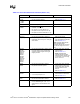
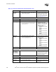
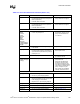
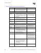
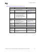
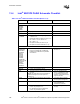
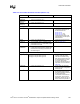
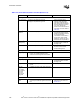
Table 13-4. Intel
®
P64H2 Schematic Checklist (Sheet 2 of 4)
Checklist Items Recommendations Comments