
Intel Xeon Processor and Intel E7500/E7501Chipset Compatible Platform Design Guide

Schematic Checklist
228 Intel
®
Xeon™ Processor and Intel
®
E7500/E7501 Chipset Compatible Platform Design Guide
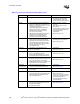
VCCSENSE • Leave No Connect. • Isolated low impedance
connection to processor core
VCC_CPU.
• Refer to Section 11.2.2.
VID[4:0] • Individually pull-up to 3.3 V using 1 k
Ω
resistor, provided a VRx 9.1 compliant
regulator is used and recommended
comparator is used.
• Should be routed individually from each
processor to the voltage regulator supplying
its VCC_CPU supply.
• Compare VIDs from both processors using
glue logic to disable VR/VRM if VIDs of both
processors do not match.
• Processor drives these signals to
indicate maximum core voltage
allowed. SM_VCC must be
correct and stable before the VRM
should rely on these outputs.
• Refer to Section 5.6.1,
Section 5.6.4, and Section 11.2.
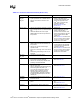
VSSA • Use discrete RLC filter to provide clean
power.
• Isolated ground for internal PLLs.
• Refer to Section 11.2.7.
VSSSENSE • An isolated low impedance
connection to processor core
VSS.
• Refer to Section 11.2.2.
VCC_CPU
Decoupling
• Minimum of capacitors per processor with
the following package and electrical
properties:
• 10 - 560 µF (OSCONs): ESR < 12 m
Ω;
ESL < 3.1 nH
• 20 - 22.0 µF (Ceramic 1210 package):
ESR < 10 m
Ω; ESL < 1.1 nH
• 4 - 1.0 µF (Ceramic 0805 package):
ESR < 8 m
Ω; ESL < 0.702 nH
• 3 - 0.1 µF (Ceramic 0603 package):
ESR < 6 m
Ω; ESL < 0.630 nH
• Refer to Section 11.2.9.1 and
Section 11.2.9.2.
• Contact your capacitor vendor to
verify these electrical properties.
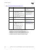
NOTES:
1. A[35:3]# pins on the processor correspond to HA[35:3]# pins on the MCH.
2. ADSTB[1:0]# pins on the processor correspond to HADSTB[1:0]# pins on the MCH.
3. D[63:0]# pins on the processor correspond to HD[63:0]# pins on the MCH.
4. DSTBN[3:0]# pins on the processor correspond to HADSTBN[3:0]# pins on the MCH.
5. DSTBP[3:0]# pins on the processor correspond to HADSTBP[3:0]# pins on the MCH.
6. REQ[4:0]# pins on the processor correspond to HREQ[4:0]# pins on the MCH.
7. The RESET# pin on the processor corresponds to the CPURST# pin on the MCH.
8. The TRDY# pin on the processor corresponds to the HTRDY# pin on the MCH.
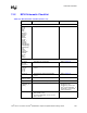
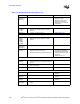
Table 13-1. Processor Schematic Checklist (Sheet 4 of 4)
Checklist Items Recommendations Comments