
Intel Xeon Processor and Intel E7500/E7501Chipset Compatible Platform Design Guide

Intel
®
82870P2 (P64H2)
134 Intel
®
Xeon™ Processor and Intel
®
E7500/E7501 Chipset Compatible Platform Design Guide
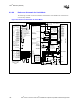
8.2.7.8 SMBus Address Considerations
In dual-slot parallel mode, the SMBus address strap pins in Table 8-14 are multiplexed as Hot-Plug
control signals HxRESETA# and HxBUSENB#. Therefore, it is recommended that the following
technique be used for determining an SMBus address. Pull the PAGNT5 (RESETA#) signals to
ground through a 100
kΩ ± 5% resistor. This keeps the reset signal active until the P64H2 is ready
for it to become deasserted. Pull the PAGNT4 (BUSENB#) signals to 3.3 V through a
10
kΩ ± 5% resistor. The P64H2 will be able to drive this signal to ground when the signal must be
asserted.
Keep in mind that this limits the range of addresses you can achieve. Using this technique, the
address is fixed if operating in dual-slot parallel mode on both controllers.
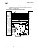
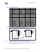
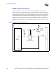
NOTE: The pin names shown in the Intel P64H2 block are slot pin names. For dual-slot parallel mode, refer to
Table 8-19 for the corresponding P64H2 pin name.
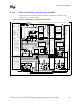
Figure 8-18. Dual-Slot Parallel SMBus Circuit
Slot 1
10 kΩ
3.3 V
HXBUSENB#
HXRESETA#
HXRESETB#
HXBUSENA#
Switch
Switch
Slot 2
100 kΩ
Intel
®
P64H2