
Intel Xeon Processor and Intel E7500/E7501Chipset Compatible Platform Design Guide

Intel
®
82870P2 (P64H2)
130 Intel
®
Xeon™ Processor and Intel
®
E7500/E7501 Chipset Compatible Platform Design Guide
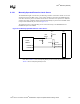
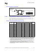
8.2.6.7 SMBus Address Considerations
In single-slot parallel mode, the SMBus address strap pins listed in Table 8-14 are multiplexed with
Hot-Plug control signal HxRESETA#. Therefore, it is recommended that the following technique
be used for determining an SMBus address. Pull the PAGNT5 (RESETA#) signal to ground
through a 100
kΩ ± 5% resistor. This will keep the reset signal active until the P64H2 is ready for it
to become deasserted. Pull the PAGNT4 (HxBUSENB#) signal to 3.3 V through a 10
kΩ ± 5%
resistor. The P64H2 will be able to drive this signal to ground when the signal must be asserted.
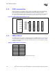
NOTE: The pin names shown in the Intel P64H2 block are hot-plug slot signal names. For single-slot parallel
mode, refer to Table 8-17 for the corresponding P64H2 pin name.
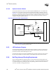
8.2.6.8 Pull-Ups/Pull-Downs in Single-Slot Parallel Mode
All PCI signals should follow the PCI Local Bus Specification, Revision 2.2 pull-up requirements
whether they are multiplexed or not. All unused input signals should be pulled to 3.3 V through an
8.2
kΩ ± 5% resistor to keep them from floating.
Table 8-17 defines which multiplexed signals are to be used with single-slot parallel mode. Note
that whether in single- or dual-slot parallel mode, all signals from Table 8-17 are actually
multiplexed even though only the signals listed in Table 8-18 are used. As a result, all unused input
signals listed in Table 8-17 must be pulled to 3.3 V through an 8.2
kΩ ± 5% resistor to keep them
from toggling.
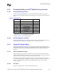
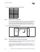
Table 8-18. Hot-Plug Controller Output Signal Reset Values
Signals Reset Value
PxGNT[5:3] 011
HPx_SOC 0
HPx_SIC 0
HPx_SOL 0
HPx_SOLR 0
HPx_SOD 0
HPx_SORR# 1
HPx_SOR# 0
HPx_SIL# 1
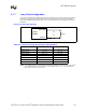
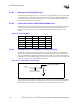
Figure 8-16. Single-Slot Parallel SMBus Circuit
HXBUSENB#
HXRESETA#
Slot 1
100 kΩ
3.3V
Intel
®
P64H2
10 kΩ