
Voltage Regulator Module (VRM) 10.2L Design Guidelines


VRM – Mechanical Guidelines
30 Voltage Regulator Module (VRM) 10.2L Design Guidelines
7.4 Mechanical Dimensions - PROPOSED
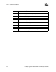
The mechanical dimensions for the VRM 10.2 module and connector are shown in Figure 7-1.
7.4.1 Gold Finger Specification
The VRM board must contain gold lands (fingers) for interfacing with the VRM connector that is
1.50 mm ±0.2 mm [0.059” ±0.008”] wide by 6.00 mm [0.236”] minimum long and spaced
2.50 mm [0.098”] apart. Traces from the lands to the power plane should be a minimum of
0.89 mm [0.035”] wide and of a minimal length.