
Intel Xeon Processor Multiprocessor Platform Design Guide

84
Processor Power Distribution Guidelines
A complete analysis of this circuit's currents into and out of the center node, as in Equation 11, will
provide the final GTLREF of the circuit. n is the number of I
REF
inputs supplied by the divider.
Equation 8-2. Node Analysis
Plugging in for the currents and rearranging gives:
Equation 8-3. Node Analysis in Terms of Voltage
Which leads to:
Equation 8-4. Solving for GTLREF
The worst case GTLREF should be analyzed with IREF at the maximum and minimum values
determined for the number of loads being supplied. If the number of loads can change from model
to model because of upgrades, this should be taken into account as well. Analyze Equation 8-4 with
R
1
and R
2
at the extremes of their tolerance specifications.
8.12.1 GTLREF [3:0]
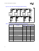
Intel recommends two voltage dividers for each processor and one for the chipset component.
Assume a maximum of 15 µA of leakage current per load. Note that these leakage currents can be
positive or negative.
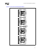
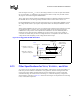
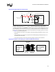
The following discussion illustrates using a single voltage divider to support two GTLREF Loads
assuming V
CC
of 1.7 V. Using 1% resistors for the voltage divider in Figure 8-14 make R
1
a 100 Ω
resistor, and use 49.9 Ω for R
2
. This creates a static usage of 10.7 mA (1.7 V / 149.9 Ω) per voltage
divider. After looking at all combinations of R
1
and R
2
(above and below tolerance) and I
(± 30 µA), the worst case solution for Equation 8-4 can be found with I
REF
at 30 µA, R
1
at the low
end of its tolerance specification (99 Ω), and R
2
at the high end of its tolerance specification
(50.4 Ω). This yields:
Equation 8-5. Resistor Tolerance Analysis
IR IR n I() ()
21
=+×
REF
REF
12
CC
In
R
GTLREF
R
GTLREFV
×=−
−
12
REF2CC
11 RR
InRV
GTLREF
+
×−
=
V
R
EF
= 1.7/50.4 - .000030 = 1.1255V
1/50.4 + 1/99