
Intel Xeon Processor Multiprocessor Platform Design Guide

51
Mechanical and EMI Design Considerations
Mechanical and EMI Design
Considerations 7
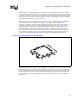
7.1 Retention Mechanism Placement and Keep-Outs
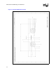
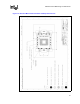
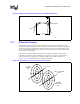
The retention mechanism (RM) requires two keep-out zones, one for the EMI ground pads and
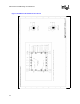
another for a limited component height area under the RM as shown in Figure 7-1. Figure 7-2
shows the relationship between the RM mounting holes and pin one of the socket. In addition it
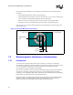
also documents the ground pads and keep-out zones. Figure 7-3 details the ground pad locations
and the associated limited height areas due to the ground frame.
The EMI ground pads under the retention mechanism should have a minimum of 8 vias connecting
the pad to the baseboard ground plane. The retention holes should be a non-plated hole.
The ground pads for the EMI ground frame should have a minimum of 6 vias each connecting the
pads to the ground plane. The suggested via size is 0.012. This should allow sufficient clearance to
route traces between the vias on the secondary side of the PB or on internal layers.