
Intel Xeon Processor Multiprocessor Platform Design Guide

102
Methodology for Determining Topology and Routing Guidelines
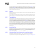
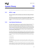
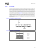
Figure 9-7. Traditional Method of Calculating Rising Edge to Rising Edge Flight Time,
Assuming a Linear Edge from V
IL
Through V
IH
at the Receiver
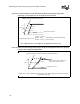
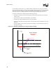
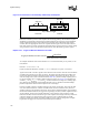
Figure 9-8. Method of Calculating Setup Flight Time When the Edge Rate Seen at the Receiver
is Slower than the Minimum Edge Rate
Vih
Threshold
Vil
Ta(Vih)
Tb(Vih)
Ta(th)
Tb(th)
Ta(Vil)
Tb(Vil)
−
−
−
)()(
)()(
)()(
VilTaVilTb
thTathTb
VihTaVihTb
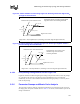
Flight Time = Worst case
Reference driver into reference load
Signal at at receiver
(Assuming a linear edge through
Vil and Vih)
Note: Flight time skew is the difference in flight time between 2 nets
Vih
Threshold
Vil
Tb(extrapolated)
Reference driver into reference load (no package
parasitics)
Signal at receiver
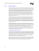
Flight Time = Tb (extrapolated)- Ta
(Assuming a linear edge through
Vil and
Vih that is slower
than the Min. edge rate)
Ta
Min. edge rate (rate at which the
receiver was characterized)