
Intel Xeon Processor and Intel E7500/E7501Chipset Compatible Platform Design Guide

Intel
®
Xeon™ Processor and Intel
®
E7500/E7501 Chipset Compatible Platform Design Guide 37
Baseboard Requirements
3.3 Platform Component Placement
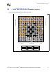
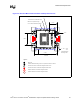
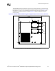
Figure 3-4 illustrates the component placement for a typical tower optimized board. Table 3-2 lists
the assumptions used for the component placement. Refer to www.ssiforum.org for detailed
information on the SSI (Server System Infrastructure) specification.
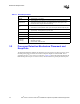
Table 3-2. Assumptions for System Placement Example
System
Configuration
Assumptions
Form Factor (SSI Specification) Number of PCB Layers Assembly
DP Server SSI Entry (12”x13”) 8 Layers Double Sided
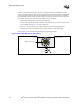
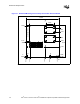
Figure 3-4. Typical 2U Rack Optimized Board System Placement Example