
Intel Xeon Processor with 800 MHz System Bus Thermal/Mechanical Design Guide

Intel® Xeon™ Processor with 800 MHz System Bus Thermal/Mechanical Design Guidelines 35
Thermal/Mechanical Reference Design
2.5 Electrical Requirements
2.5.1 Fan Power Supply (Active CEK)
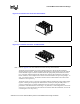
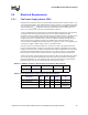
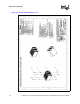
Initially the boxed Intel Xeon Processor with 800 MHz System Bus will be introduced with a 3-pin
active fan heatsink solution, This heatsink solution requires a constant +12 V supplied to pin 2 and
does not support variable voltage speed control or 3-pin PWM control. Fan RPM is automatically
varied based on the T
INLET
temperature measured by a thermistor located at the fan inlet. See
Table 2-18 for details on the 3-pin active heatsink solution connectors.
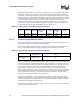
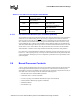
A new 4-pin PWM/T-diode controlled active fan heatsink solution will replace the 3-pin thermistor
controlled solution after initial boxed Intel Xeon Processor with 800 MHz System Bus
introduction. This new solution is being offered to help provide better control over pedestal chassis
acoustics. This is achieved though more accurate measurement of processor die temperature
through the processor’s temperature diode (T-diode). Fan RPM is modulated through the use an
ASIC located on the serverboard, that sends out a PWM control signal to the 4th pin of the
connector labeled as Control. This heatsink solution also requires a constant +12 V supplied to pin
2 and does not support variable voltage control or 3-pin PWM control.
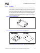
If the new 4-pin active fan heatsink solution is connected to an older 3-pin baseboard CPU fan
header it will default back to a thermistor controlled mode, allowing compatibility with existing
designs. It may be necessary to change existing baseboard designs to support this new 4-pin active
heatsink solution if PWM/T-diode control is desired. It may also be necessary to verify that the
larger 4-pin fan connector will not interfere with other components installed on the baseboard.
The fan power header on the baseboard must be positioned to allow the fan heatsink power cable to
reach it. The fan power header identification and location must be documented in the suppliers
platform documentation, or on the baseboard itself. The baseboard fan power header should be
positioned within 177.8 mm [7 in.] from the center of the processor socket.
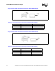
Table 2-17. PWM Fan Frequency Specifications (4-Pin Active CEK Heatsink)
Description Min Frequency Nominal Frequency Max Frequency Unit
PWM Control
Frequency Range
21,000 25,000 28,000 Hz
Table 2-18. Fan Specifications (3-pin & 4-pin Active CEK Heatsink)
Description Min
Typ
Steady
Max
Steady
Max
Startup
Unit
+12 V: 12 volt fan power supply 10.8 12 12 13.2 V
IC: Fan Current Draw N/A 1 1.25 1.5 A
SENSE: SENSE frequency 2 2 2 2
Pulses per fan
revolution