
Intel Xeon Processor Multiprocessor Platform Design Guide

77
Processor Power Distribution Guidelines
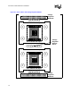
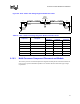
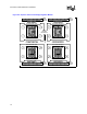
8.10.3 Multi-Processor Component Placement and Models
This section provides recommended placement diagrams and lump electrical model schematics for
four processor systems. Baseboard impedances are estimates based on minimum copper weight
requirements.
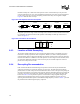
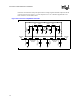
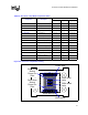
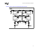
Figure 8-8. “Row” Pattern with Voltage Regulator Module Schematic
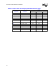
Table 8-3. “Row” Pattern with Voltage Regulator Module Schematic Values
Component Description
Values
Resistance Inductance Capacitance
Outside OSCONs Bulk Capacitors 12 m
Ω / 6 3.1 nH / 6 6 × 560 µF
Inside OSCONs Bulk Capacitors 12 m
Ω / 8 3.1 nH / 8 8 × 560 µF
L1 VRM A – Proc A south 75
µΩ 20 pH -
L2 Proc A north - sense 75
µΩ 20 pH -
L3 Proc B south - sense 75
µΩ 20 pH -
L4 VRM B – Proc B north 75
µΩ 20 pH -
Voltage
Regulator
Remote Sense
L1
Voltage
Regulator
Module A
Proc A South
Side Input
Proc B South
Side Input
Proc A North
Side Input
Proc B North
Side Input
L4
Voltage
Regulator
Module B
Inside
OSCONs
Outside
OSCONs
Outside
OSCONs
L2 L3