
Intel Xeon Processor Multiprocessor Platform Design Guide


54
Mechanical and EMI Design Considerations
Intel recommends the following for constructing the mounting holes for the enabled retention
mechanism.
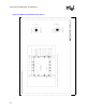
• All four RM mounting holes must have ground pad rings.
• Ground pad annular ring should be no less than 125 mils wide. Try to cover the entire keep-out
zone, if possible. See the following illustration for better dimensions.
• Place 8-12 vias in the annular ring, which connects the pad to internal ground planes.
• Anodizing or any form of insulated coating of the heat sink is strongly discouraged.
Refer to Figure 7-3 for specific details regarding the ground pads that are required to utilize this
reduction technique.
7.2 Electromagnetic Interference Considerations
7.2.1 Introduction
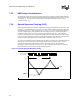
As microprocessor amperage and speeds increase, the ability to contain the corresponding
electromagnetic radiation becomes more difficult. Frequencies generated by these processors will
be in the low gigahertz (GHz) range, which will impact both the system design and the
electromagnetic interference (EMI) test methodology.
This section is intended to provide electrical and mechanical design engineers with information
that will aid in developing a platform that will meet government EMI regulations. Heatsink
grounding, processor shielding, differential and spread spectrum clocking and the test methodology
impact to FCC Class B requirements are specifically discussed.
Designers should be aware that implementing all the recommendations in this guideline will not
guarantee compliance to EMI regulations. Rather, these guidelines may help to reduce the
emissions from processors and motherboards and make chassis design easier.
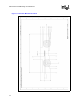
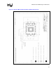
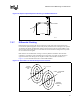
Figure 7-3. Retention Mechanism Ground Ring
80 mils
15 mils
125 mils
RM Mounting
hole
Ground Rin
g
VIA